SAFETY CRITERIA
1 Attention:beforebeginninganykindofprocedureofinstallation
is absolutely necessary to read all this manuall.
2 Test/Controlthatthe performancesofthe actuatorauswerto
your installation needs.
3 Besidescontrolthat:
• The gare hinges are in good conditions and perfectly fattened.
• The gate has mechanicall stops in the opening and the closing.
INSTALLATION ADVICE
Connections:
• See the “Scheme functional ” and refer to the control central
scheme.
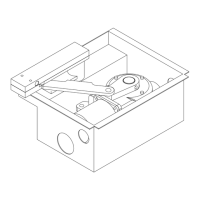
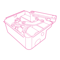
• Theelectriccableintheexitfromtheactuatormustbetight,
butdoanamplecurvetowardsthebottominordertoavoidthe
refluxintheinsideoftheactuatoritself.(Fig.Q)
• The adjustment must be effected when the device has no
powersupply.
• Foresee a omnipolar breaking device near to the apparatus (the
contact must measure at least 3 mm).
Alwaysprotectthepowersupplyusinga6Aautomaticswitch,
ora16Asingle-phaseswitchses.
• Thepowersupplylinesthemotors,tothecontrolunitandthe
connectionlinestotheouttsmustbeseparatedtoavoidtrou-
bleswhichcouldgenerateproblemsintheinstallationworking.
• Anyoutts (of control orsafety)eventually connectedto the
control unit must be tension free.
Spare parts:
• Use esclusively original spare parts.
• Thebatteriesshouldbeputwithindustrilwasteandnotwith
domesticrefuse.(Lawn.475/88).
Installation:
• Inordertousecorrectlytheproductandtoexcludethepossibi-
lity of injury or damage, refer to the "Generals" page enclosure,
whichisanintegratedpartofthismanual.
• The use of this equipment must be in observance of the safety
standardsinforceinthecountrywhereitisinstalled,aswellas
the standards governing proper installation.
• Togetherwiththismanualisprovidedalabelshowingmanu-
facturer'snameandproductreference:pleasestickitinsighton
the equipment for future reference.
Warranty:
• Thewarrantysupplied bythe manufacturerbecomesvoidin
the event of interference, carelessness, improper use, lightening
damage,powersurchargesorusebyunqualiedpersonnel.
• Thewarrantywillalsobecomeinthefollowingevent:Failureto
observetheinstructionsgiveninthemanualssuppliedwiththe
product.
The application of any part in a manner differing from that pro-
videdforcurrentlegislationortheuseofsparepartswhichare
unsuitableand/ornotapprovedbymanifacturer.
• The manifacturer cannot be helb responsible for damages due
to impropre or unresonable use.
INSTALLATION INSTRUCTION SEQUENCE
1 Before the installation, analyse the risks referring to the chapter
“Generalities”ofthisinstructionsmanual,llthetechnictable
and eliminate the risks noticed.
Incaseofmorerisks,foreseetheinstallationwithsecuritysystem.
2 Testthesecuritylawsofthe“SecurityCriteria”.
3 Identify the right actuator and left actuator.
4 Control all the components.
5 Identifythexingpointonthegateandthenonthepillar.
6 Fixthe“Anchorplate”atthelittlepillar.
7 Fixthegearmotortothe“Anchorplate”.
8 Unlock the actuator.
9 Fixthearticulatedarm.
10 Fit the support S3 to the gate
11 Connectthewiresaccordingthe“Functionalswinggatescheme”.
12 Connect the control unit and all the accessoires
13 Program the radio receptor
14 Programworkingtimes
Incaseofbadworking,seethe“Anomaliesandadvises”.
IfyoudonotndanysolutioncallthenearestAssistencecentre.
GB
ELECTRO LOCK
Pleasenoticethattheelectriclockmustbeinstalledontheswing
thatopensrstandmustbeconnectedwiththeterminalboardof
the control unit.
Positionoftheelectriclock:(Fig.B)
Position 1:Lockbetweenthewings
(inthiscaseisnecessarytousetheboltRT15onthesecondwing).
Position 2: Lock in the floor (in this case the utilisation of the bolt
is not necessary).
Remembertoremovethelockoratleastblockthelockinopening
positionandtakeawayalltheboltsoflock.
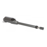
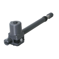
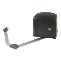
RIGHT OR LEFT ACTUATORS (Fig. A)
TheactuatorsaresuppliedinRightorLeftversion.
Rightorleftareestablishedlookingthegatefromthesidewhere
the actuators are installed, if the hinges are on the right the actuator
is right, if they are on the left the actuator is left.
Conseguentelytheactuatormust be installedwiththe exitpin,
positioned in the hinges of the gates.
DETERMINATION OF FIXING MEASURES
To determinate the clamping point it is necessary pay attention to
this:
• A = 300 mm (Fig. C)
Maximumdimensionbetweentheaxisofthegateandtheedge
of the pillar.
• B = 30 mm (Fig. C)
Maximumdimensionfromtheanchorplatetotheedgeofthe
pillar.
(to avoiod the possible brake of the edge)
• D = 14 mm (Fig. F)
Vertical distance from the clamping point of the clamp S3 on
the gate, to the anchor plate on the little adge.
Gate xed in the middle of the pillar (Fig.D)
Inthiscasethemaximunalopeningcornerofthegateis90°.
Gate xed on the edge of the pillar (Fig. E)
Inthiscasethegatecanbeopenedwithacornergreaterthan90°.
Payattentiontothis:growingthedistanceoftheactuatorfromthe
edgeofthepillarmeasureB,theopeningangleofthegategrows.
HEIGHT INSTALLATION (Fig. G)
Calculate the height of the actuator installation according to the
gate's shape and the fastening possibility.
a) If the gate has a big structure you can position it at any height
withnolimits.
b) If the structure is light it necessary to put the operator as much
as possible to the centre of the gate (in heigt).
Position 1 Central beam of the gate
Position 2 Stiffen of the gate
FIXING THE ANCHOR PLATE
Todawelortosoldeltheanchorplateonthelittlepillarneartothe
gate, paynig attention to the quotes indicate above.
Incaseofclampingwithexpandingloosepieces,usemetallicloose
pieces Ø 13 mm and consider that the loose piece has to be
positionedat30/35mmdistantfromtheedgeofthelittlepillarto
avoid the possibility of broke.
Incaseofwollingpillarusechemichalloosepieces,orresineloose
pieces,oraconnectlywolledclamp.
Itispossibletousetheplate,intwodifferentways,forrightorleft
actuator,accordingtotheparticularyexigences.(Fig.H/I)
8
Advantage - rev. 14_06_2022
 Loading...