GB
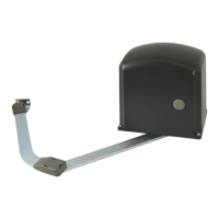
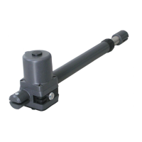
MOTOR POSITION AND ARTICULADED ARM
1 Putthemotorontheanchorplate,payingattentiontotheexit
pinofthemotorwhichmustbeturnedtotheinteriorofthegate.
2 Put together the three parts of the articulated arm. ( Fig. M)
Theuprightarmwiththearm,andthearmwiththeclampS3
withscrewsT.E.12x35,selflokinghutsM12andwastherØ12
mm.
3 Unclamp the motor using the normal key. (Fig. L)
4 Fitthearticulatedarmintothemotorshaft(pictureL)andxit
throughtheTEbolt8x16andtheØ32washer.
5 ExtendthearticulatedarmtilltopositionatethexingclampS3
on the gate.
Thebestsituationisgivenwhenthearmformsalittleangleas
showninFig.C.
6 WeldscrewtheclampS3tothegate.
LIMIT SWITCH REGULATION(g.R)
1 Set the motor thrust
2 Give an opening impulse.
3 Whentheleavesreachtheopeningmechanichallimitswitchit
isnecessarytoplacetheCamofthemicrolimitswitchandto
xitscrewingitdownwithoutforcing.
4 Give a closing impulse.
5 Whentheleavesreachtheclosingmechanichallimitswitchit
is necessary to put theCam of the limitswitch and x itby
screwingitwithoutforcing.
6 Regulatethemotorthrust(asperthecontrolunitinstructions)
ItispossibletoStoptheworkingstrokeofthegatewithaforce
of150N(about15Kg)
N.B.Thiskindofmotorhasbeenstudiedtobeusedwithmicro-limit
swith.
Ifyoudonotusethemunclampthemotorcanbemoredifcoult
and you could have a more rapid damage of the mechanical parts.
MECHANICAL STOP (Fig. A)
At this point you need to position the machanical Stop to proced
respectively,tothewing’sclosingandopeningStop.
EXTERNAL OPENING GATE
Ifthegateopenstilltheexterioritispossibletoputtheactuator
betweenthetwopilar.
Gate xed in the middle of the pillar (Fig. N)
Inthiscasethemaximunalopeningcornerofthegateis90°.
Gate xed on the edge pillar (Fig. O)
Exterior xed the pillar (Fig. P)
Inthiscasethegatecanbeopenedwithacornergreaterthan90°.
Payattentiontothis:reducingthedistanceoftheactuatorfromthe
edgeofthepillarmeasureA,theopeningangleofthegategrows.
RELEASE OF THE ACTUATOR
- To keep out the cap on the fore part of the motor. (Fig. L)
- Toputandtowheelof90°intimesensetheendowedkey.
Not it is possible to open and to close the gatem handly.
- Tore-hooktheactuator,towheelinthecontrarysensetheendowed
key.
It is not necessary the gate is in a particurety position, because at the
rstorderallthevolversarerestored.
ES
CRITERIOS DE SEGURIDAD
1 Antes de empezar cualquiera operacion de montaje es sumamente
necesario leer todo este manual.
2 Averiguar que las prestaciones del actuador comprado respondan
avuestrasexigenciasdeinstalación.
3 Ademásaveriguarque:
• Las branches de la cancelas se encuentr en buen estado y
sean perfectamente engrasadas.
• La cancela haya sido dotados de bloqueos mecánicos en
abiertura y en el cierre.
CONSEJOS PARA LA INSTALACIÓN
Conexiones:
• Ver “Esquema funcional de puerta a hoja” y referirse a los
esquemas de la central de mando.
• El cable electrico a la salida del motor no debe estar tirante,
debe hacer una curva amplia hacia abajo para evitar el regreso
de agua al interior del mismo motor. (Fig. Q)
• Todas las conexiones se deben efectuar sin alimentación
eléctrica.
• Prever un dispositivo de repartimiento omnipolar cerca del
aparato. (los contactos tienen que ser de poro menos 3 mm)
Proteja siempre la alimentación con un interruptor automático
de 6A, o bien con otro monofásico de 16A completo de fusibles.
• Las lineas de alimentacion a los motores, a la central e las lineas
de coligamiento a los accesorios deben ser separadas por evitar
disturbios los cuales poderian causar problemas de funcionamiento.
• Cualquier aparato (de propulsión y de seguridad) eventualmente
coligado a la central debe ser libre de tension.
Piezas de recambio:
• Utilice solamente piezas de recambio originales.
• No eliminar las baterias como basuras urbanos sino como basuras
industriales.(Leyn.475/88)
Modalidad de instalación:
• Paraunusoadecuadodelproductoyparaexcluircualquiera
posibilidad de daños a personas, animales o cosas, ver la hoja
anexa"Generalidades"queformapartedelpresentemanual.
• El uso de este equipo debe respetar las normas de seguridad
vigentes en el paísenelque que se instala, además de las normas
de buena instalación.
• Se adjunta a estas instrucciónes una pegatina con el nombre
del producto y del fabricante; por favor coloquele sobre el producto
de forma visible.
Garantía:
• La garantía del fabricante caduca en caso de mal uso, dincuria,
uso impropio, rayos, sobrecarga de tensión, o utilización por
partedepersonalnocalicadoprofesionalmente.
• Sepierdecualquierderechodegarantíacuando:Noserespetan
lasinstruccionesdelosmanualesanexosalosproductos.
La aplicación, aunque sea en un solo detalle, en modo que no
responda a la legislación vigente o la utilización de repuestos
noadaptadosy/onoexpresamenteaprobadosporfabricante.
• El fabricante no puede considerarse responsable por posibles
daños causados de usos impropios e irracionales.
SECUENCIA DE INTALACION
1 Antes de empezar la instalación efectuar el “Analisy de los riegos”
refeirindose a las “Genaralidades” pertenencen a este manual,
rellenar el esquema técnico y eliminar los riesgos relativas.
En el caso en que permanezcan unos riesgos, efertuar la instalación
con sistemas de seguridad de completamento.
2 Averiguar las normas de seguridad de los “Criterias de seguridad”.
3 IdenticarelactuadorDerechoyelactuadorIsquierdo.
4 Averiguar todos los componientes.
5 Identicarelpuntodejacióndelacancelaydespuéssobreelpilar.
6 Fijar la plancha de anclaje sobre la el pillar.
7 Fijar el motor sobre la plancha de anclaje.
8 Desbloquearelactuador.
9 Posicionar el brazo articulado.
10 Fijar la estafa S3 sobre la cancela.
11 Tirar los cables como en el “Esquema funcional de puerta a hoja”.
12 Colegar la central y todo los accessorios.
13 Colegar el receptor de radio
14 Programar los tiempos de funcionamiento.
9
Advantage - rev. 14_06_2022
 Loading...