6
F1
K3 K6
K4 K5
F2
VR1 VR2
J1 J3 J7 J6
K1 K2
S3
OL CL PT LOOP POWER
PUSH
S5
LEARN
OPEN STOP CLOSE
T1
J9
OFF ON
OFF ON
1
4
2
3
5
6
11
10
9
12
8
7
S1
S4
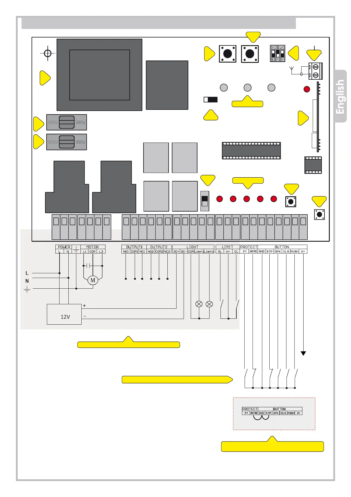
9. AC WIRING DIAGRAM (230/115Vac)
Lights supply
Blinker
Limit switch OPEN
Limit switch CLOSE
Loop detector/Safety edge
Photocell CLOSE, N.C.
GND - Common
STOP push button N.C.
12V dc 8W max
START - STOP
Close
Open
LED WORK
LED WARNINGS
FACTORY WIRING
WIRING BY THE INSTALLER
1 = Transformer
2 = F1, fuse 0,2 A
3 = F2, fuse 5 A
4 = VR1, force
5 = VR2, automatic closing
6 = S1, DIP-switch terminals
7 = J2, aerial
8 = Receiver
9 = LEARN, transmitter storage
10 = Start commands
11 = Lights disconnector
12 = J9, obstacle detection (keep to ON)
The control unit comes from factory
with no. 2 bridges on N.C. contacts
Lights