8
BRG1
K3K4
K1
U2
VR1 VR2
K2
S3
DS2 DS3 DS4 DS5 DS1
PUSH
LEARN
OPEN STOP CLOSE
T1
LEARN
ON OFF
VR3
JP1 JP3 JP5
U3 Q8
S2
C1
C6
U4
F1
U1
S1
S4
1
5
4
2
3
6
10
8
7
9
LED1 LED2 LED3
V1
LED4
U6
U5
J1
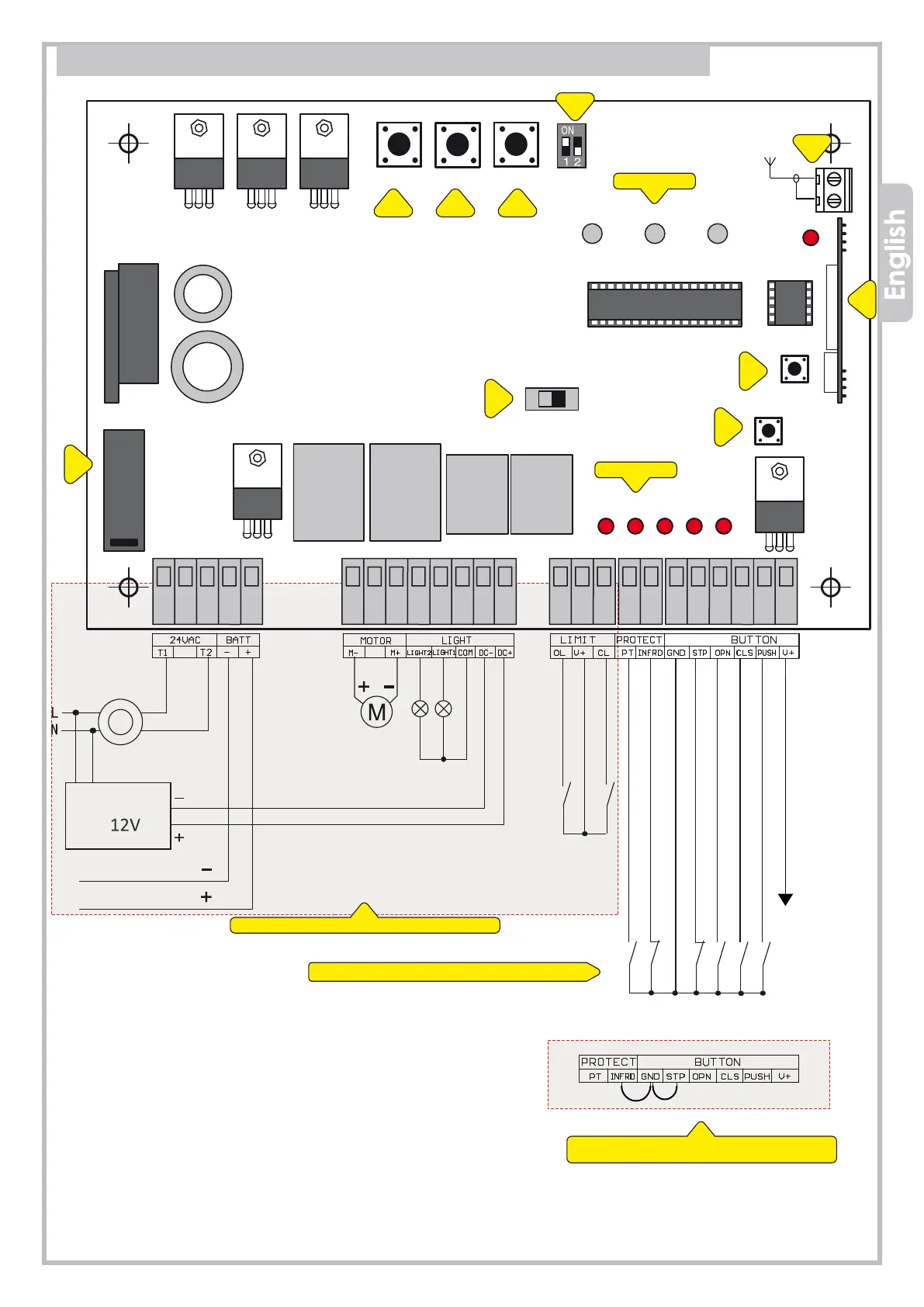
10. DC WIRING DIAGRAM (24V DC)
1 = F1, fuse 8 A
2 = VR1, automatic closing
3 = VR2, force in opening
4 = VR3, force in closing
5 = DIP-switch
6
= Aerial
7 = Radio receiver
8 = LEARN, transmitter storage
9 = Start commands
10 = Lights and blinker disconnector
FACTORY WIRING
WIRING BY THE INSTALLER
The control unit comes from factory with
no. 2 bridges on N.C. contacts
LED WORK
LED WARNINGS
Blinker
Lights
Limit switch OPEN
Loop detector/Safety edge
Photocell (CLOSE) N.C.
GND - Common
STOP push button N.C.
Power 24V dc 8W max
Star commands
Close
Open
TIME
OPEN_FORCE CLOSE_FORCE
MOTOR
TRANSFORMER
LIGHTS POWER
BATTERY 24V
Limit switch CLOSE