SAFETY CRITERIA LOCKED ACTUATOR BRACKETS S2 (Fig. F)
1 Attention: before starting any kind of procedure is absolutely necessary to read all The actuators can be locked myaster 3/4/5. In some cases - as indicated in table 1 and for particular installation is suitable to use
this manual. Please notice that the electric lock must be installed on the wing that opens first and bracket S2.
2 Test/Control that the performances of the actuator correspond to your installation must be connected with the terminal board of the control unit. Position of the electric Each bracket has one squared plate with dimensions 130x130x6 mm, with 4 holes of
needs. lock: (Fig. N). Ø12 mm and one 112x94x55 mm with 3 holes of Ø12 mm.
3 Check that: Position 1: Lock between the wings (in this case is necessary to use the bolt RT15 on Instructions for installation
• The gate hinges are in good conditions and perfectly fastened. the second wing). Screw the plate to the pillar with strong dowels
• The gate has mechanical stops in the opening and the closing. Position 2: Lock in the floor (in this case the utilization of the bolt is not essential). - Weld the bracket to the plate as in Fig. F
Remember to remove the lock or to block the lock in opening position and take away - Remember that the measures A and B are referred to the hinges axis of the gate
INSTALLATION ADVICE all the bolts of lock. and the rotation axis.
Connections:
• See the “Operal diagram” and refer to the control central scheme. RIGHT AND LEFT ACTUATORS (Fig. D) FRONT BRACKET’S FIXING
• The electric cable in the exit from the actuator must not be tight, but has to do an The actuators are supplied in Right or Left version. Fix the position of bracket S3 as follows:
ample curve towards the botton to avoid the reflux in the inside of the actuator. Right or left are established looking the gate from the side where the actuators are - Close the gate's wing.
(Fig. O) installed, if the hinges are on the right the actuator is right, if they are on the left the -
• The adjustment must be done without power supply. actuator is left.
• Foresee an omnipolar breaking device near to the apparatus (the contact must
measure at least 3 mm) Always protect the power supply using a 6A automatic DETERMINATION OF FIXING MEASURES
switch, or a 16A single-phase switch fuses. Gate fixed in the middle of the pillar (Fig. A)
• The power supply lines to the motors, to the control unit and the connection lines In this case the maximal opening angle of the gate is 90°.
to the outfits must be separated to avoid troubles which can cause problems in the - The correct functioning can be obtained putting the fixing brackets at the
installation working. measures indicated in the table above pictureAand B .
• Any outfits (of control or safety) eventually connected to the control unit must be In the case of difficulty to install do as follows:
tension free. - Measure the level D
Spare parts: (distance between the hinges’ axis and the pillar’s edge)
• Use esclusively original spare parts. - Look at the table 1, in the part related to the model of your operator untill the part MECHANICAL STOP (Fig. D).
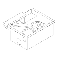
• Throw away the batteries as waste products. (Law n. 475/88). correspondent to level D. Now is neccesary to set the mechanical stop to put the stop in opening phase. When
Installation: - In the below table you can find the necessary indications and establish the most the gate is closed the actuator's rod may come out of maximum 335 mm for myaster
• In order to use correctly the product and to exclude the possibility of injury or suitable use of the bracket S1 (Fig. E) or alternatively braket S2 (Fig. F). 3, of maximum 435 mm for myaster 4, and of maximum 535 mm for myaster 5.
damage, refer to the "Generals" page enclosed, which is an integrated part of this These quotes are calculated in order to obtain an average tangential speed that does When the gate is open, the rod must be out of minimum 55 mm. (Fig. M)
manual. not exceed of 12 m/minute.
• The use of this equipment must be in observance of the safety standards in force Gate fixed on the edge pillar (Fig. B) EXTERNAL OPENING GATE
in the country where it is installed, as well as the standards governing proper way In this case the gate can open with an angle superior to 90° (max. 120°) In case of external opening is possible to put the actuator towards the internal side.
of installation. - The correct functioning for a 90° deegrees opening is obtained
putting the In this case the quote A (distance between the axe of the hinges and the rotation axe
Warranty: backets to the measures indicated in the table above pictureAand B. of the actuator) has to be measured towards the center of the gate (Fig. N).
• The warranty supplied by the manufacturer becomes vain in the event of - In order to open the wing with a bigger angle measure A has to be superior to It is also necessary to modify the bracket S2 to adapt it to the new fixing position.
interference, carelessness, improper use, lightening damage, power surges or measure B. If you do not want to reduce the lenght of the passage, you can put the actuator in the
use by unqualified personnel. The best solution is to increase measure A of the same dimension of wich must be superior part of the gate, at a height of minimum 2 mt.
• The warranty will also become vain in case of failure to observe the instructions diminished the measure B. The position of the front bracket can be founded with the method indicated upon, with
given in the manuals supplied with the product, in case of application of any part in the wing of the gate in open position.
a different way from what established by current legislation, or the use of spare HEIGHT INSTALLATION Due to the motor's power, all the fastenings must be sturdy.
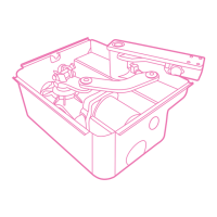
parts not suitable and/or not approved by manifacturer. Determine the height where the actuator must be installed according to the gate's
• The manufacturer cannot be considered responsible for damages due to shape and the fastening possibility. (Fig. G) RELEASE OF THE ACTUATOR
improper or unreasonable use. a) In case of sturdy structure you can position the actuator at any height with no - Insert the key (supplied in the kit) and rotate it of 90° many times towards the
limits. center of the gate. (Fig. P)
INSTALLATION INSTRUCTION SEQUENCE b) If the structure is light is necessary to put the operator as near as possible to the - In this way the gate may be opened or closed manually.
1 Before the installation, analyse the risks referring to the chapter “Generalities” of centre of the gate (in height). - Rotate the key in the opposite direction to clasp the actuator.
this instruction manual, fill the
technic table and eliminate the risks noticed. Position 1 Central beam of the gate The gate do not have to be in a particular position: at next start all previous value will
In case of more risks, foresee the installation with security system. Position 2 Reinforcement of the gate The distance between the base of the actuator be restored.
2 Test the security laws of the “Security Criteria”. collar and the floor must be more than 10 ÷15 cm.
3 Identify the right actuator and the left actuator.
4 Control all the components. BRACKET FIXING
5 Identify the fixing point on the gate and then on the pillar. Bolt or weld the bracket S1 or S2 on the gate's side pillar remember that the
6 Verify point “D” measuresAand B refer to the gate hinges axis and to the actuator's rotation axis.
7 Adapt the bracket S1 o S2 following “Table1” In case of fastening by expansion bolts, use Ø13 mm metal bolts and place the bolt at
8 Anchor the actuator to the bracket S1 o S2. no less than 30÷35 mm from the pillar's edge, to avoid breaking it. (Fig. H)
9 Unclamp the actuator In case of masonry pillars, use chemical or resin bolts or a cementated bracket.
10 Anchor the bracket S3 on the gate - The bracket S1 (Fig. E) has two versions: bracket S1 right end bracket S1 left;
11 Anchor the manina of the piston to the bracket S3. each one should be used with its actuator.
12 Stretch the wires as in the ”Operal diagram” - Fasten the actuator to bracket S1 as indicated in “Fig. I”: remember that the
13 Connect the control unit and all the accessoires threaded hole of the rotating pivot PR1 must be turned down.
14 Program the radio receptor
15 Program working times
In case of bad working, see the “Anomalies and Advises”
If you do not find any solution call the nearestAssistance centre.
Release the gearmotor.
-
.
- Retract the stainless tube approximately for 2cm.
- Place the S3 bracket into the ram with the PR1 pin and fixing (pict. L)
(NB: lower part)
- Lean the S3 bracket on the leaf keeping the ram perfectly horizontal (you may
better use
a spirit-level) and fix the bracket with a screw or weld it.
NB: Check the manual opening of the leaf before definitively fixing the brackets
and make sure that the leaf opens completely.
Let the inox ram rotate completely until reaching the mechanical stop (max.
stroke)
ENGLISH
 Loading...