Hardware Overview and Installation
ORiNOCO
®
802.11n & 802.11ac Access Points - Hardware Installation Guide 15
2.2.4.3 Step 3: Plugging in the Cables
Cabling with Power Adapter (Not supplied with the product package)
To plug in the cables by using a 5V DC power adapter:
• Connect one end of the CAT5e/CAT6 Ethernet cable (not supplied with the product) to the device’s ethernet port and
the other end to a PC.
• Plug the barrel of the power cable into the device’s power socket, only after the device installation is complete.
Cabling with Gigabit PoE (Not supplied with the product package)
To use Power over Ethernet (PoE), we recommend you to use our Gigabit Ethernet PoE adapter ORiNOCO 1-Port Active
Ethernet DC Injector (See Optional Accessories) and follow the following guidelines:
• Connect one end of the ethernet cable to the Data In port of the DC Injector and the other end to a PC.
• Connect one end of the second ethernet cable (not supplied with the product) to the device’s ethernet port, and the
other end to the Data & Power Out Port of the DC Injector, only after the device installation is complete.
: PoE should be installed only in an indoor network, maintaining a controlled temperature.
Serial Connection
Optionally, you can connect a nine-pin, male-to-female serial cable to the console port/DB9 connector of the device for
debugging and management.
:
• Use a straight-through ethernet cable, if you intend to connect the device to a switch, hub, or patch panel.
• Use a cross-over ethernet cable or adapter if you intend to connect the device to a single computer.
• The pin6 on RJ11 connector is used for power consumption and debugging. This connects internally to the 12VDC.
• If power is drawn from this input pin, then the radio might malfunction.
2.2.4.4 Step 4: Power On the Device
To power on the device, plug in the power cord into a power outlet. There is no ON/OFF switch on the device. To disconnect
power:
• Unplug the RJ45 connector from the Data & Power Out port on the DC injector, if using the Gigabit Ethernet PoE.
• Unplug the power cable from the power socket of the device, if using power adapter.
2.2.4.5 Step 5: View LEDs
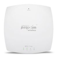
When the device is powered on, it performs startup diagnostics. When startup is complete, the LEDs show the operational
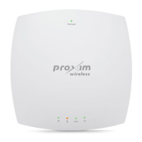
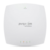
state of the device. Tabulated below is the behavior of the four LEDs on the device:
LED Behavior Color
Power LED Glows green when the device is switched ON.
Ethernet LED Glows red when the ethernet interface is connected to a 100 Mbps
link.
Glows green when the ethernet interface is connected to a 1000 Mbps
link.
 Loading...
