Tsunami
®
800 and 8000 Series - Hardware Installation Guide 26
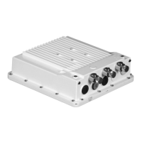
Connect the grounding wire, which is supplied with the product package, to the device as shown below:
¯
Figure 2-11 Ground the device
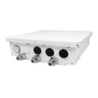
Step 12: Power ON the Device
Plug in the power cord into a power outlet after having connected the PoE Injector and the device using Cat5e/Cat6 cable.
There is no ON/OFF switch on the device. To disconnect power, unplug the RJ45 connector from the “PWR LAN-OUT” port
on the PoE injector.
:
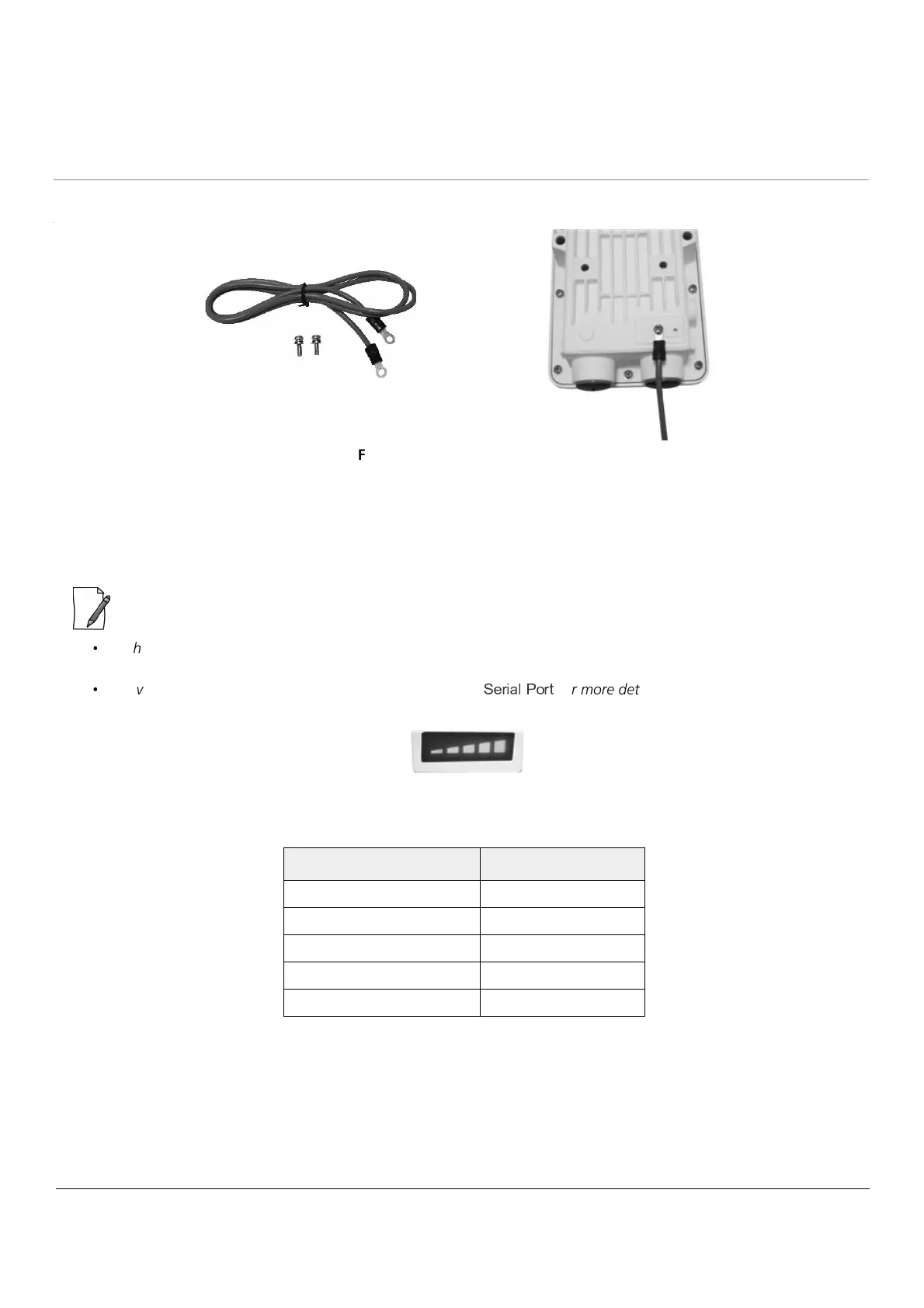
When you power ON the device, LEDs on the scaling mask glow. The more LEDs on the scaling mask glow, better is
the signal. For better signal strength, try adjusting the position of the device.
Device can also be powered via serial port(12VDC).Refer
`
O L R K a ] ^ L Y
for more details.
The number of LEDs glowing and their corresponding SNR ranges are as follows:
Step 13: View LEDs
When the device is powered on, it performs startup diagnostics. When startup is complete, the LEDs show the device’s
operational state. The LEDs are available at the device’s Ethernet connector inside the enclosure. You can see the LEDs
through the Ethernet connector. The LEDs will not be visible if the RJ45 connector is weatherproofed.
Number of LEDs Glowing SNR Ranges
1 1-12
2 13-18
3 19-24
4 25-30
5 SNR > 30
 Loading...