This document serves as a Quick Start Guide for the Pryor 4000 Series Marking Machines, providing an introduction to their functions, operation, and safety guidelines. The full manual is available for download from www.pryormarking.com/products/4000-controller.
Function Description
The Pryor 4000 Series Marking Machines are designed for dot peen and scribe marking, capable of creating permanent marks on a wide range of workpieces. The system consists of a controller with an integrated touchscreen, an optional remote start/stop box, and a marking head. It supports various marking styles, sizes, and depths, making it versatile for different industrial applications.
System Overview
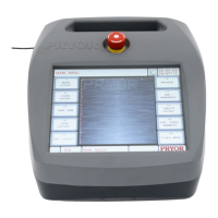
The core of the system is the controller, which features an integrated touchscreen for primary operation. Operators can navigate through menus, input data using on-screen forms and an on-screen keyboard. If an external keyboard is connected, options can be selected using cursor keys and the Enter key, or by pressing function keys F1-F10.
The marking head, the physical component that applies the mark, consists of two main parts: the base and column (for column-mounted systems) and the X-Y marking head. The gap between the marking unit and the base can be easily adjusted to accommodate various workpieces and fixtures.
Marking Capabilities
The machines can create marks in straight lines or arcs. Each layout can contain up to 40 lines of characters, with up to 100 characters per line. Each line can have its own character size, marking force, and specified horizontal and vertical position (for straight lines) or radius and start angle (for arc marking).
Layout Creation and Management
Users can create, check, and save multiple layouts in the controller's memory. Before actual marking, a trial run feature allows users to verify the mark's position, and a preview function displays the entire marking area with the entered text.
Important Technical Specifications
Weight of Machine and Ancillary Equipment (Approximate):
- BenchDot 300-150 EZA Marking Unit (inc. Base and Column): 54kg
- BenchDot 150-150 EZA Marking Unit (inc. Base and Column): 44kg
- BenchDot 100-100 EZA Marking Unit (inc. Base and Column): 40kg
- MarkMate Marking Unit (Inc. Base and Column): 13kg
- 4000 Series Marking Controller: 7kg
- Circumferential Fixture: 10kg
- Magnetic Chuck: 10kg
Character Size (Height):
- Range: 0.15 mm to 999.90 mm (0.006” to 40”)
- Steps: 0.15 mm (0.006”) (for 5x7 dot and varidot style, dependent on machine type)
Marking Force:
- Range: 0 (no mark) to 14 (deep mark). Some marking heads may have restrictions on marking force.
X and Y Position Resolution:
Character Width:
- Can be specified independently of height. If set to 0.0, it's calculated automatically.
- Range: 0.00 mm to 999.90 mm (40”).
Angle:
- For straight marks: Specifies rotation around XY position (-359 to +359 degrees).
- For arc marks: Specifies the start angle of the text (-359 to +359 degrees).
Radius:
- For arc marks: Specifies the inside radius of the arc. Ignored for straight marks.
Z-axis (Optional):
- For electric Z-axis: Specifies position before marking.
- For pneumatic Z-axis: 0.0 retracts, 1.0 extends. Movement occurs after XY movement for a layout line.
Length:
- For straight marks: Maximum length of the mark. Character width condensed if necessary. If set to 0, it's ignored.
- For arc marks: Maximum length in degrees.
Font Styles:
- 5x7 dot: Standard 5x7 dot matrix. 0.15 mm (0.006”) minimum size.
- 5x7 varidot: Characters formed from lines of dots, with adjustable spacing. Not ideal for small characters.
- 7x9 dot: 7x9 dot matrix. 0.20 mm (0.008”) minimum size.
- 5x9 OCR dot: Dot matrix characters conforming to OCR standard. 0.20 mm (0.008”) minimum size.
- 5x9 OCR varidot: Vector characters conforming to OCR standard. Not ideal for small characters.
- Vector: Used for Fast Pneumatic and Scribe Machines. Continuous lines, similar to 5x7 font.
- HPGL: Used on dot and scribe machines. Simple vector font, can be overridden by downloading HPGL files per letter.
- Minimum sizes are for 40 steps/mm, based on 1 step between dots.
Varidot (Dot Spacing):
- Electric solenoid dot marking: 5 to 255 steps.
- Pneumatic solenoid dot marking: 50 to 255 steps.
Repeat Dot:
- Allows marking each dot multiple times (1-9) for deeper marks, resulting in slower speeds.
Usage Features
Getting Started:
- Setting Up: For column-mounted systems, a sturdy bench is required, and the machine base should be fastened using the two mounting holes. Before first use, the stylus nozzle, solenoid core (slug), stylus, and spring must be fitted, and the stylus checked for free movement.
- Connections: All connectors on the rear of the controller are clearly labeled, simplifying the connection process.
- X1-X/Y: Connects directly to the Marking Head.
- X2 - Z/C: Connects directly to the Z-axis. If a Circumferential axis is used, connect it to the circ axis first, then the Z-axis cable to the secondary port on the circ axis (optional).
- X3 - I/O 0: Digital I/O port (8 digital inputs, 6 digital outputs) for external device interfacing (optional).
- X4 - I/O 1: Expansion Digital I/O port (additional 8 inputs, 6 outputs) (optional).
- X5 - Ethernet: Ethernet TCP/IP port for connecting to TCP/IP communication networks.
- X6 - USB Type B: USB communication port for connecting to a Windows PC (creates a virtual COM port).
- X7 - USB Type A: USB socket for USB flash memory or USB keyboards.
- X8 - EXT ESTOP: External emergency stop connector, replacing the built-in ESTOP for remote system interfacing (optional).
- X9 - RS232: RS232 Serial Port (9-pin) for interfacing with PCs, PLCs, barcode scanners, and other serial communication devices.
- X10 - START-STOP: Remote Start/Stop for connection to the controller's remote start/stop cycle button panel.
- X11 - FIELDBUS / INDUSTRIAL ETHERNET: Anybus interface for control by automation systems using various industrial Ethernet or fieldbus interfaces (Profibus, ProfiNet, Ethernet/IP, EtherCAT, DeviceNet, Modbus, etc.) (optional).
- X12 - I/O 2 & X13 - I/O 3: Expansion Digital I/O ports (additional 8 inputs, 6 outputs each) (optional on Integrated 4000 controller).
- Important Note: Ensure Marking Head and C/Z Motor connectors are firmly connected and screwed in place. Never attach or remove connectors when the controller is powered up.
Operation:
- Power On: Switch the system on using the switch on the rear of the controller. The machine will not operate unless the emergency stop button is untwisted and released. The Main menu will be displayed upon power-up.
- Menu Navigation: Options can be selected by pressing buttons on the touchscreen or by using cursor keys and Enter/function keys with a connected keyboard.
- Animated Help Topics: The controller includes an animated help feature accessible from the main menu's information button. These topics simulate marking and trial runs, with all marking head movements disabled during help topic execution.
- Creating a Layout: Select "F8) Create layout" from the Main menu. The layout edit screen allows users to input text, set character size (e.g., 3.0 mm), and adjust force.
- Preview Function: Select "F6) Preview" from the main menu to display the entire marking area and the entered text.
- Zooming: Use cursor keys to move a green box over the text and press the zoom-in button. Press ESC to return to the zoomed-out view. The green box can also be dragged on the touchscreen.
- Magnification: Zoom in/out buttons (magnifying glass icons) increase/decrease magnification. An auto-zoom button fits the mark to the screen.
- Dot Size Adjustment: Buttons allow modification of dot size in the preview to better represent the actual mark for the material, without affecting the actual mark.
- Grid Overlay: A button toggles a grid overlay at 1mm or 10mm intervals, depending on the zoom level.
- Trial Run: Select "F3) Trial run" from the main menu. The marking head homes and then moves to the top left of the first line, tracing the envelope of each line without marking the workpiece.
- Trial Run Controls: Buttons on screen allow exiting the trial run, selecting previous/next lines, and tracing lines with stops at corners.
- Jogging: Buttons allow moving the object one jog step up/down/left/right (mm), jogging Z-axis up/down (mm), changing jog step size (0.1mm, 1mm, 10mm), rotating clockwise/anticlockwise by one jog step (degrees), and increasing/decreasing text size by one jog step (mm).
- Layout Line Selection: Lines in the layout can be selected by pressing on the text in the list or on the mark in the preview screen. The head will move through intervening lines to avoid collisions.
- Mark Movement: Marks can be moved by dragging them in the preview after selection.
- Marking a Layout: Position the workpiece under the marking head and adjust the gap between the stylus and the workpiece (approx. 2 mm / 0.08"). Select "F1) Mark layout" or the green button on the remote control. Increase gap or force for deeper marks.
- Stopping the Marker: The red button on the remote control (if used) aborts marking without losing the current layout. The emergency stop interlock on the controller stops marking by removing all power from motors and punch, while keeping other electronics running.
Line Parameters (Contents):
- Text: Marks text exactly as it appears.
- Serial: Increments a serial number after each layout mark.
- Global serial: Replaced by a global serial number when the layout is marked.
- Variable: Can be modified from the Edit Variables screen or via a communication port.
- Global variable: Replaced by a global variable when the layout is marked.
- Time/date: Inserts time/date information at specified places.
- Logo (Dot/HPGL Smooth/HPGL Sharp): Specifies the name of a dot or HPGL logo.
- I/O control: Contains commands for programmable digital inputs and outputs.
- Barcode: Replaced by text from a barcode reader.
- Comms Command: Transmits text out of the RS232 port to a third-party device (e.g., barcode printer).
- DataMatrix: Encodes text into a Data Matrix code.
- Data Entry via Prompt: Replaces text with variable information entered on-screen or from barcode scanners.
- Obliterate Data Matrix: Renders a Data Matrix code unreadable by crossing it out and filling its timing pattern.
- Serial via Prompt: Allows entering a starting serial number and increments it for the number of cycles entered by the user (with Data Entry via Prompt mode and MultiMark enabled).
- Variable / Serial: Treated as a Serial Number but can be modified via communication port in select layout mode.
- Special: Reserved for special applications.
Editing Layouts (Editing Keys):
- Up/Down Arrows: Move to previous/next line.
- Left/Right Arrows: Move left/right one character.
- Home/End Keys: Move to beginning/end of an entry.
- Page Up/Down: Move up/down several lines.
- Up/Down Arrows (with parameters): Move up/down one line in the layout (only when editing parameters).
- X (Delete under cursor): Deletes character under the cursor.
- X (Delete left of cursor): Deletes character to the left of the cursor.
- Insert Space: Inserts a space.
- Line Parameter Screen Toggle: Moves to/from line parameter screen.
- Back/Escape: Leaves current screen/goes back one menu.
- Cut/Paste Menu: Accesses the cut/paste menu.
- Layout Parameters: Edits layout parameters (offsets, home method, autosense gap).
- Mark Preview: Views mark preview.
On-screen Keyboard Features:
- Aa button: Toggles between upper and lower case letters.
- £$%& button: Cycles through special character keyboard layouts (not available for filenames or when loading/saving files).
- Aa button (after special characters): Returns to standard alphanumeric keyboard layout.
Maintenance Features
Health & Safety:
- Handling: Care must be taken when moving or handling the equipment to prevent damage or injury. It is advisable for two people to lift the machine using the base and column, not by the cover.
- Noise Emissions: Noise emitted by the machine may exceed 70dB(A)Leq depending on the workpiece. If noise exceeds regulations, noise control methods (e.g., ear defenders, machinery guards) should be used.
- Electrical Hazards: To prevent electrical shock, do not remove the cover of the controller or marking head. There are no user-serviceable parts inside; refer servicing to qualified personnel. Only connect the controller to the correct supply voltage, which is clearly marked on the rear.
- Possible Hazards whilst Operating: Motors are low force and inertia, posing low risk when used as instructed. Care should be taken near the marking head during setup, operation, or maintenance. Keep all objects other than the workpiece away from the marking area. Eye protection should be worn.
- Risk Assessment (UK): Employers must comply with general risk assessment requirements in the Management of Health and Safety at Work Regulations and ensure work equipment is suitable for its intended operation as per the Provision and Use of Work Equipment Regulations.
- International Users: Users outside the UK must comply with local legislation and implement adequate control measures to reduce risk.
- Installing and Commissioning: It is essential to read the user manual(s) prior to use.
- Disposal and Decommissioning: The LCD contains hazardous liquid and should be disposed of according to current regulations. The controller contains a lithium battery, which also requires disposal in accordance with current regulations.
- Stability: Bench machines are provided with bolt holes in the base for fastening them down.
- Emergency Stop: An emergency stop is built into the controller (not to be confused with the remote start/stop pendant). Pressing it immediately stops all mechanical movement and disconnects power from drive circuits. To release, twist the button. Releasing it does not reactivate the machine until appropriate commands are executed from the touchscreen.