Do you have a question about the Pryor Marktronic 3000 BenchDot 100-100DP and is the answer not in the manual?
Emphasizes firm work piece holding for quality marks, suggesting interchangeable fixtures.
Describes character size ranges and considerations for large characters.
Discusses how material hardness affects mark depth and stylus life.
Explains factors influencing dot mark depth: force, gap, material, and stylus angle.
Details how varying stylus tip angle affects life, depth, and readability.
Instructions for setting up column mounted systems and connecting components.
Explains that a layout contains text, size, force, and XY position information.
Describes how to modify text, size, force, and XY position of a layout.
Explains how to set the main mode of operation and enable hardware options.
Guides the user through creating a new layout and entering text.
Explains the trial run function to trace the marking path without marking.
Details how to position the workpiece and initiate marking.
Specifies the character style options available for marking.
Details character text limits, size ranges, and XY positioning.
Details parameter for specifying dot spacing in marking.
Section detailing how to edit existing layouts.
Specifies linear/arc marking modes for text.
Introduces extensive parameters associated with each line in a layout.
Lists keys used for editing layouts and their functions.
Explains the Contents parameter specifying the line's purpose (text, serial, etc.).
Explains automatic increment/decrement after marking, and types (global, layout).
Describes the unique serial number shared across all layouts.
Details serial numbers specific to each layout and their configuration.
How to set the controller's time, date, and date format.
How to incorporate live time/date information into a layout using commands.
How to place HPGL logos in a layout and set size/spacing.
Guides on using the controller's simple editor to draw dot logos.
Discusses creating and transferring logos from CAD packages.
How to place a dot logo into a layout and set its size.
Explains the USB port acts as a virtual COM port for PC connection.
Lists support for external control systems like PLCs via field buses.
Allows external devices to select, mark, and modify layouts remotely.
Commands to transmit text or non-printable ASCII characters via serial.
Describes the optional Ethernet port for network connectivity.
Details the functionality of the optional Ethernet Port.
How external equipment can input text directly into the layout via barcode.
Operating the controller by sending character codes to simulate key presses.
How to select layouts and replace variables using serial commands.
Transmitting data from serial/USB/Ethernet port during a layout.
Allows sending batches of items to the controller for marking.
How inputs/outputs can be configured for different modes.
External equipment selects and marks one of 31 layouts.
Verifies correct operation of inputs and outputs through test menus.
Allows use of programmable commands and remote marking.
How to interface switches and external 24V signals to inputs.
Allows commands in a layout to use inputs and outputs.
Saving controller memory to a PC for safety and recovery.
Allows defining XYZ zero positions offset from absolute home positions.
Controller marks at different speeds affecting quality and speed.
Creating and marking Data Matrix codes via line contents.
Using tilde character as command for non-printable characters in DataMatrix.
Step-by-step procedure to configure and test Data Entry via Prompt mode.
Protects menu options with a two-level password system.
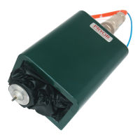
Describes the marking head's fixed XY home position and Z-axis zero.
Combining multiple layout lines onto a single line.
Performing soft or hard resets to restore default configuration.
Similar to link command but specifies start/end character positions.
Machine automatically senses part height for accurate marking depth.
How the stylus finds part height and the sensor's repeatability.
Cleaning AutoSense emitter/receiver lenses and checking stylus movement.
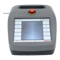
Common controller faults like screen flashing, no power, or rebooting.
Suggests hardware fault or corrupted memory, advises reset procedures.
Check mains fuse and follow procedure for internal fuses.
| Brand | Pryor |
|---|---|
| Model | Marktronic 3000 BenchDot 100-100DP |
| Category | Industrial Equipment |
| Language | English |