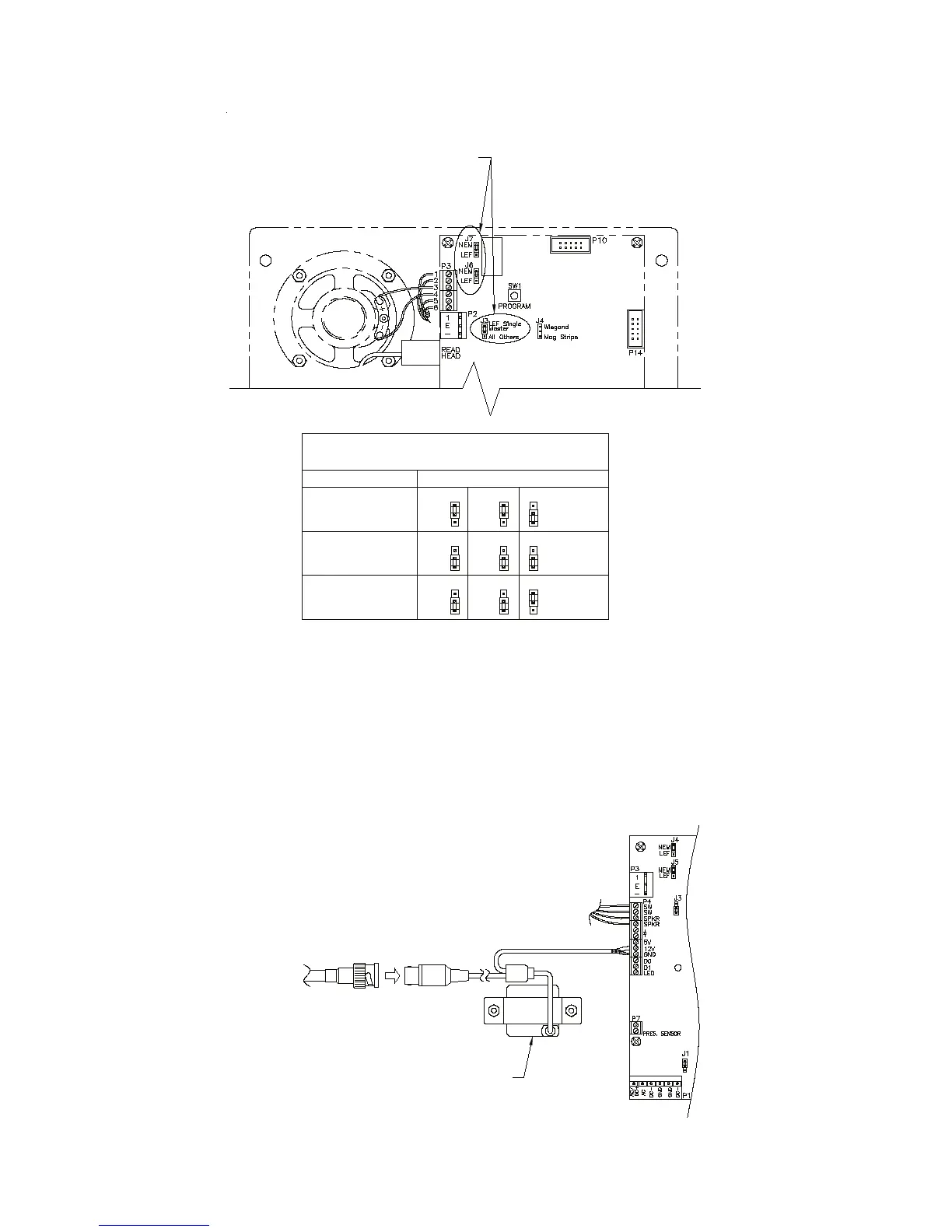
EasyManua.ls Logo

PTI security systems VP keypad controls entry - VP Series Keypad Camera and Jumper Settings

PTI security systems VP keypad controls entry
40 pages
Print Icon
To Next Page IconTo Next Page
To Previous Page IconTo Previous Page
Loading...
14 15
Figure 16
• Pinhole camera. Connect the video signal cable using RG59U
cable and BNC type connectors. This will give the best possible
picture from the keypad camera. Pinhole camera power is supplied
by the keypad circuit board. In some situations, it may be necessary
to install a video amplier or a video isolator depending on how
the video system is installed. See Figure 17 for information on
connecting the video camera.
Figure 17
TO VIDEO
DISPLAY
EQUIPMENT
CAMERA
(OPTIONAL)
INTERCOM TYPE APEX JUMPER CONFIGURATION
INTERCOM JUMPER
CONFIGURATION TABLE
SEE INTERCOM JUMPER
CONFIGURATION TABLE
FOR PROPER
JUMPER PLACEMENT
LEF (SINGLE
MASTER STATION)
LEF (ALL BUT
SINGLE MASTER
STATION)
NEM (ALL)
NEM
LEF
NEM
LEF
LEF Single
All Others
J3
Master
J7 J6
NEM
LEF
NEM
LEF
LEF Single
All Others
J3
Master
J7 J6
NEM
LEF
NEM
LEF
LEF Single
All Others
J3
Master
J7 J6

Related product manuals