The PTronik ECo Master Controller is a device designed for controlling dust collectors, primarily by pulsing solenoid valves based on time or differential pressure settings. This quick start guide provides basic information for its installation, setup, and operation.
Function Description:
The ECo Master Controller manages the cleaning cycle of a dust collector. It can operate in two main modes:
- Manual Mode (Sequential Timer): In this mode, the controller operates as a basic sequential timer, pulsing solenoid valves at predefined intervals.
- Auto Mode (On-Demand Cleaning - ODC): In this mode, the controller uses a differential pressure sensor to monitor the pressure across the filter bags. It initiates cleaning cycles (pulsing solenoid valves) when the differential pressure reaches a high threshold and stops when it falls below a low threshold, optimizing cleaning efficiency and saving energy.
The controller is capable of pulsing up to 240 solenoid valves, depending on the setup and the number of extension cards connected. It also tracks the number of pulses saved when operating in differential pressure mode compared to a sequential timer, indicating efficiency gains.
Important Technical Specifications:
- AC Input (for DC Solenoid Version): 100-240VAC
- DC Input (for DC Solenoid Version): 10-30VDC
- AC Input (for AC Solenoid Version): 100-240VAC
Solenoid Output:
- DC Solenoid Version: Fixed at 24VDC output.
- DC Solenoid Version (DC Input): Output voltage is identical to the input voltage (e.g., 10VDC in, 10VDC out; 24VDC in, 24VDC out).
- AC Solenoid Version: Output voltage is identical to the input voltage (e.g., 240V in, 240V out; 110V in, 110V out).
Differential Pressure Measurement:
- Units: mmH2O (0-250mm H2O), inH2O (0-10" water), KPa (0-2.5KPa).
- Sensor: Can use either an internal differential pressure sensor (DP) or an external differential pressure sensor (XDP).
Pulse Settings:
- Pulse On-Time: User selectable from 1ms to 999ms.
- Pulse Off-Time (Interval between pulses): User selectable from 1s to 999s. Two off-time settings (OffTime1 and OffTime2) are available for different differential pressure levels.
Connectivity:
- Modbus RTU: For communication and integration with other systems.
- Extension Cards: Allows for expansion to control more valves.
- Input Sensors: Connections for various input sensors.
- Output Relays: For general control outputs.
- 24VDC Connections: Specifically for tube cleaning valves.
Usage Features:
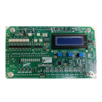
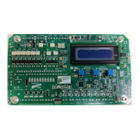
User Interface:
- LCD Screen: Displays operational data, settings, and alarm states.
- Three-Button Interface: Used for navigation, setting adjustments, and mode selection.
- Left Button: Manually changes the state between Halted and Pulsing (only in manual mode).
- Middle Button: Accesses alarms, maintenance mode, and controller settings (Menu).
- Right Button: Toggles between Manual and Auto modes.
Main Run Page: Provides a real-time snapshot of the dust collector's status, including:
- Controller Model (PMC)
- Countdown to next valve pulse
- Next valve to pulse
- Percentage savings (in DP mode)
- Differential pressure sensor type (DP/XDP) and value
- Differential pressure alarm level (U Low, Low, High, Fast, Alarm)
- Alarm state (A1-A8, indicating interrupt, disabled, enabled, or activated alarms)
- Solenoid state (OK, Open Circuit, Short Circuit for the last fired valve)
- Tube cleaner count (number of times valves have fired)
- Manual halt status
- Mode of operation (Auto/Man)
- Password Protection: A default code (4) is required to access settings.
- Timer Settings:
- Total Valves: Configures the number of valves connected.
- Valve OnTime: Adjusts the duration of each pulse.
- Valve OffTime1/OffTime2: Sets the interval between pulses, with two distinct times for different DP levels (OffTime1 for Low to Fast DP, OffTime2 for Fast to High DP).
- On-Demand Cleaning (ODC) Settings:
- Pressure Units: Selects the unit of measurement for differential pressure.
- Set Pressure Levels: Defines four differential pressure levels to initiate and terminate cleaning:
- Low: Stops pulsing.
- High: Normal operation, uses OffTime1.
- Fast: Higher DP, uses OffTime2.
- Alarm: Highest DP, indicates a problem.
Installation Considerations:
- The ECo should only be installed by a suitably qualified person, adhering to all local electrical standards.
- Wiring:
- Connect AC incoming power to ENA (J103) for AC input.
- Connect DC incoming power to DCVI (J104) for DC input.
- Connect solenoid coils to SOLENOIDS (J306).
- Important Safety Notes:
- DO NOT double up solenoid valves; connect only one per position.
- DO NOT mix commons between main and extension cards to avoid valve faults.
- Differential Pressure Tubes: Connect measurement tubes to the onboard DP sensor. For pre-fitted units, bulkhead fittings will be on an external point.
- HP air supply (C) for tube cleaner (Eco-0 only).
- Clean side measurement (C or L) to the clean low-pressure side of the baffle plate.
- Dirty side measurement (D or H) to the dirty side of the baffle plate.
- DO NOT connect high pressure air into the clean or dirty side tube connections, as this will damage the sensor.
Maintenance Features:
Maintenance Mode (Accessed via Menu):
- Valve Number to Test: Allows selection of a specific valve to test.
- Pulse Test: Pulses the selected valve and reports its status:
- OK: No fault.
- OC: Open Circuit (coil not connected or burnt out).
- SC: Short Circuit (showing a short circuit).
- This mode helps in diagnosing faulty solenoid valves.
Alarm Monitoring: The controller continuously monitors differential pressure and solenoid valve states, triggering alarms for critical conditions (e.g., high differential pressure, valve faults). The alarm state is displayed on the main run page.
Further Assistance:
- A full manual is available for detailed information.
- Contact PTronik for support via phone, website, or email.