Connecting Power and Solenoid Valves
If the ECo has been purchased as a complete unit then undo the 4 dome nuts and remove
the face plate. Remove the PCB from the brass spacers to access the bottom of the board.
DO NOT double up solenoid valves, only connect one solenoid valve per position.
DO NOT mix commons between the main and extension cards if extension cards are connected.
Doing both these will cause the ECo to detect valve faults.
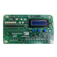
DC SOLENOID VERSION - AC input power and 24VDC
solenoid output
For this configuration the AC input voltage can be
between 100-240VAC, but the output voltage is fixed
at 24VDC
1. Connect the 100 to 240V AC incoming power
supply to terminal marked ENA (terminal J103).
This plug is removable to assist the installation
process.
2. Connect the 24VDC solenoid coils to terminal
marked SOLENOIDS (terminal J306). This plug is
removable to assist the installation process.
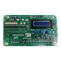
DC SOLENOID VERSION - DC input power and DC
solenoid output
For this configuration the DC input voltage can be
between 10-30VDC and the output voltage to the coils
is identical to the input voltage. So 10VDC in, 10VDC
out. 24VDC in, 24VDC out etc.
1. Connect the DC incoming power supply to
terminal marked DCVI (terminal J104)
2. Connect the 24VDC solenoid coils to terminal
marked SOLENOIDS (terminal J306). This plug is
removable to assist the installation process.
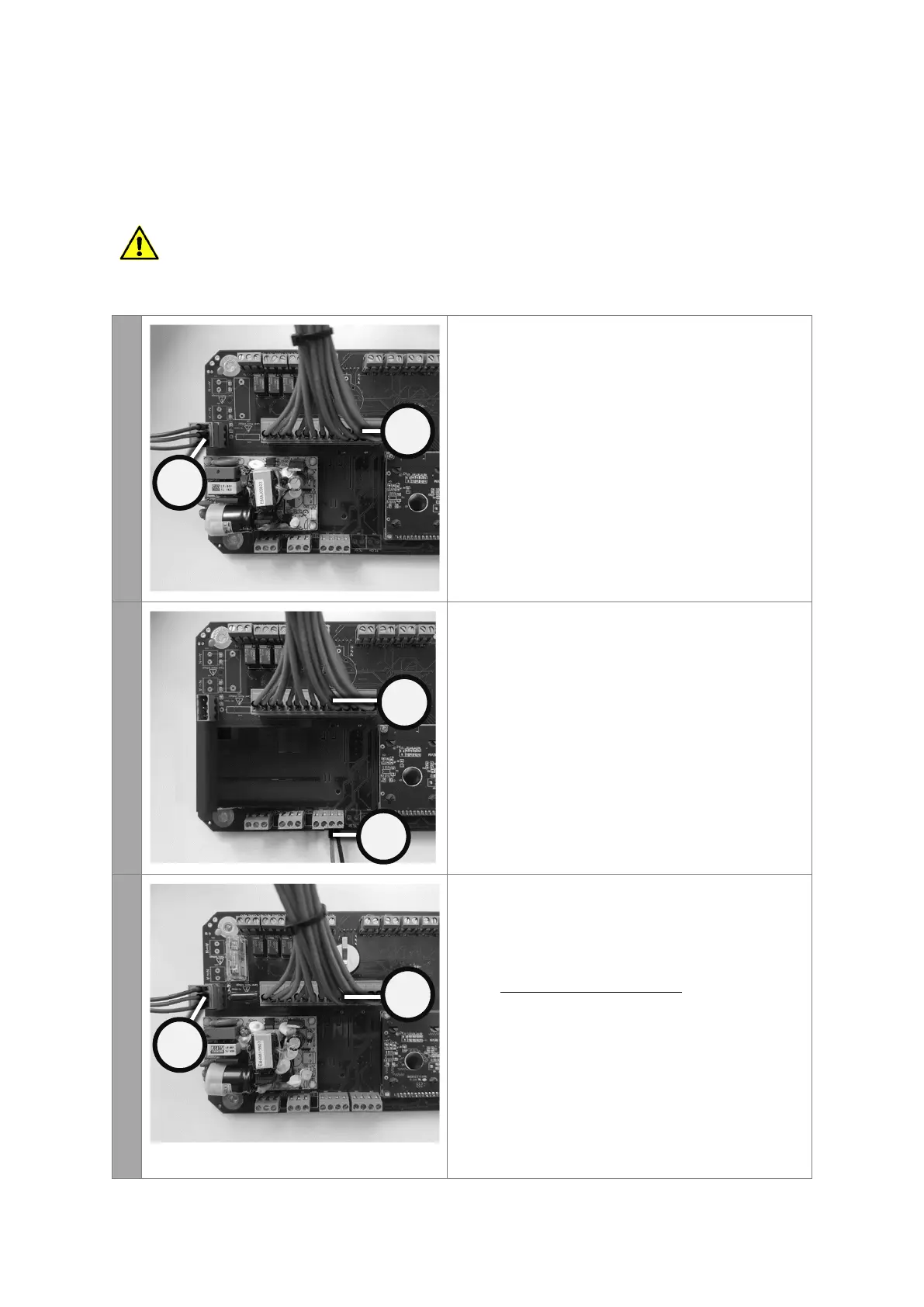
AC SOLENOID VERSION - AC power input and identical
AC solenoid output
For this configuration the AC input voltage can be
between 100-240VAC and the output voltage to the
coils is identical to the input voltage. So 240V in, 240V
out. 110V in, 110V out etc.
1. Connect the 100 to 240V AC incoming power
supply to terminal marked ENA (terminal J103).
This plug is removable to assist the installation
process.
2. Connect the 100 to 240V AC solenoid coils to
terminal marked SOLENOIDS (terminal J306). This
plug is removable to assist the installation process.
 Loading...