8
INSTALLATION - DIRECT UNITS
PLUMBING CONNECTIONS
Direct units require the following pipework connec-
tions.
• Cold water supply to and from inlet controls.
• Outlet to hot water draw off points.
• Discharge pipework from valve outlets to tundish.
ELECTRICAL SUPPLY (FIG. 6)
Pullin Evolution Solar units are fitted with two 3kW
immersion heaters as standard. It is recommended
that these should be wired via a suitable controller
to BSEN 60730. The Pullin Evolution Solar MUST
be earthed.
All wiring to the unit must be installed in accordance
with the latest IEE Wiring Regulations and the circuit
must be protected by a suitable fuse and double pole
isolating switch with a contact separation of at least
3mm in both poles. The Live and Neutral connections
are made directly onto the combined thermostat and
thermal cut-out located under the terminal cover(s)
mounted on the front of the unit. The earth connec
tion should be made to the earth connection located
to the side of the immersion heater boss(es). The
supply cable must be routed through the cable gland
located on the unit casing beneath the terminal
housing.
DO NOT operate the immersion heaters until the
Pullin Evolution Solar has been filled with water.
INSTALLATION - SOLAR PRIMARY
CONNECTION TO SOLAR PRIMARY CIRCUIT
The lower (solar) coil of the Pullin Evolution Solar
must be connected to a fully pumped solar primary
circuit. The connections are suitable for 22mm
copper pipe direct to the compression fittings
provided. The connections are also threaded 3/4”
BSP male parallel should BSP be required.
The solar primary circuit should have its own
dedicated circulating pump and safety controls which
must be installed as per the manufacturers instruc-
tions.
CONTROL OF SOLAR PRIMARY CIRCUIT
Temperature control of the Pullin Evolution Solar
must be carried out using a suitable proprietory
Solar Controller/Programmer. The cylinder tempera
ture sensing probe (supplied with the solar control
ler) should be fully insterted into the pocket provided
on the Pullin Evolution Solar and its cable secured
using the cable clamps on the controls housing (see
Fig.7).
Connection to the solar controller should be in
accordance with manufacturer’s instructions. The
solar controller should be programmed to give a
cylinder temperature of approximately 60°C
(maximum 70°C).
SAFETY
DISCONNECT FROM THE MAINS SUPPLY BEFORE
REMOVING ANY COVERS. Never attempt to replace
the immersion heater(s) other than with the recom-
mended Pullin immersion heater(s).
DO NOT BYPASS THE THERMAL CUT-OUT(S) IN
ANY CIRCUMSTANCES. Ensure the two male spade
terminations on the underside of the combined
thermostat and thermal cut-out are pushed firmly
onto the corresponding terminations on the element
plate assembly.
In case of difficulty contact service support; contact
details available at the back of this booklet.
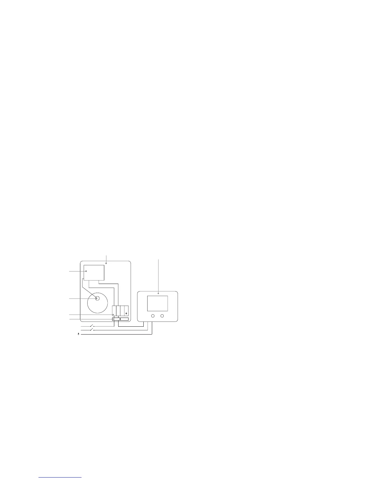
Fig. 7: Solar Control Connections
The solar controller and solar primary circulation
pump must be wired via the over-temperature cut-
out mounted in the lower solar controls housing (see
Fig. 7). This will ensure that the heat input to the
solar coil is interrupted in the event of the cylinder
over-heating. There must also be suitable check
(non-return) valves installed in the solar primary
flow and return to prevent the possibility of any
thermo-syphoning if the solar circulation is stopped.
123
SOLAR DIFFERENTIAL
CONTROLLER
(NOT SUPPLIED)
SOLAR CYLINDER
CONTROLS HOUSING
CYLINDER
TEMPERATURE
CONTROL
PROBE
TERMINAL
BLOCK
OVER
TEMPERATURE
CUT OUT
L
N
CABLE
CLAMPS