Do you have a question about the Pulnix TM-6CN and is the answer not in the manual?
Details the pinout and function of the 12-pin connector for TM-7CN and TM-7EX cameras.
Lists the pinout and functions for the 6-pin connector used on the camera.
Instructions for checking order contents, retaining packaging, and bench testing equipment.
Guidance on connecting the 12V DC power supply and power cables to the camera.
How to connect the camera's video output using a BNC connector to a monitor or VCR.
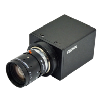
Instructions on attaching C-mount lenses and considerations for flangebacks and format.
How to use the SC-745 Shutter Controller with the camera for external shutter speed adjustment.
Explanation of controlling shutter speeds using BCD inputs and the SC-745 controller.
Description of the shutter mechanism based on substrate drain charge transfer.
Details TTL level sync and buffered pixel clock outputs from TM-7 series cameras.
Explains the basic principles of Charge Coupled Device (CCD) operation, including photoelectric conversion and charge transmission.
Details the vertical and horizontal charge transfer mechanisms within the CCD sensor using potential wells.
Provides a graph showing the relative sensitivity of the CCD sensor across different wavelengths.
Explains the differences between FIELD MODE and FRAME MODE scanning for the camera.
Instructions for connecting and testing the Sync Gen board, including jumper settings.
Steps for connecting and testing the Processor board, including jumper settings and voltage adjustments.
Procedure for connecting and testing the Imager board, adjusting Vsub voltage.
Lists factory settings for AGC/MGC, GAMMA, and FLD/FRM options.
Specifies the external sync signals (HD, VD) and input impedance requirements for TM-7EX/TM-6EX models.
Details the pin configurations for the 12-pin connector on TM-7EX/TM-6EX models.
Explains the asynchronous reset feature and its benefits for strobing applications.
Instructions for performing horizontal and vertical phase adjustments on the TM-7EX Genlock board.
Details standard input/output impedance selections for specific connector pins.
Lists jumper settings for TM-7CN and TM-7EX models for various configurations.
| Sensor Type | CCD |
|---|---|
| Video Output | Composite Video, 1.0Vp-p/75 Ohms |
| Power Supply | 12VDC |
| Image Sensor | 1/2 inch |
| Scanning System | Interlace |
| Lens Type | C/CS Mount |
| Lens Mount | C/CS Mount |
| Synchronization | Internal |
| Shutter Speed | 1/60 to 1/100, 000 sec |
| Operating Temperature | -10°C to +50°C |