5
1. Power and Audio Mute Switch.
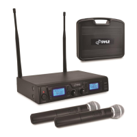
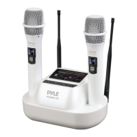
2. Antenna: Transmit the RF signal of transmitter.
3. Belt Clip: Attach the transmitter to the belt.
4. Audio Input Jack: it is suitable for lavalier system/headset system.
5. Channel Display: Indicates the frequency data of the selected channel group.
6. Gain Adjusting Volume: Adjust the transmitter audio input gain.
7. State Setting Switch: Set the using state of lavalier system(L)/headset system(H).
8. Up Function Button: Sets channel data.
9. Down Function Button: Sets channel data.
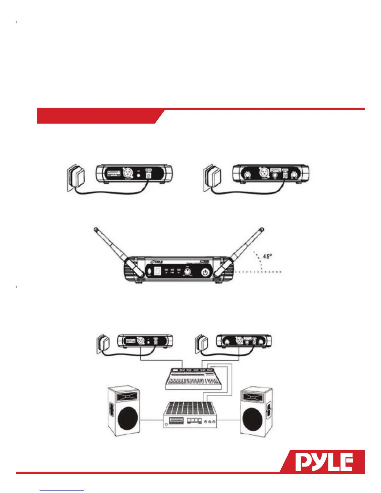
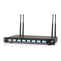
RECEIVER CONNECTIONS
1. Receiver Power Connection: Connect the AC adapter into the DC power connector on the back of the
receiver. Plug the AC adapter into a AC 120V/220V 50Hz outlet.
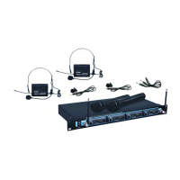
2. Antenna: Keep the position of antenna at a 45 angle from vertical, .(Shown as below)
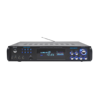
3. Audio Connection: Connect the audio cable from the audio output on the receiver to the input on your
amplier equipment.