www.PyleUSA.com
www.PyleUSA.com
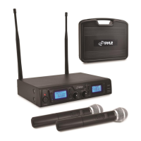
RECEIVER
OPERATION
Attach the two antennas and extend them vertically. Switch on the receiver.The red power indicator will come on. Switch on the
transmitter. The red indicator RF/Channel1, RF/Channel2, RF/Channel3, RF/Channel4 will come on to indicate signal reception.The
green AF LEVEL meters indicate the audio level. Adjust the volume of receiver, transmitters and amplier. Please switch off the
receiver, transmitters and amplier when the wireless microphone system is not being used.
5 6
RECEIVER
SQUELCH
The squelch control on the rear of the receiver is preset at the factory. If you must use the system in an area with considerable RF
interference and there is some noise from the receiver when your transmitter is off, you can adjust the squelch control so that the
system will receive the signal from your transmitter only but squelch or eliminate the unwanted background RF noise. This adjustment
can cause reduction in useable range of the wireless transmitter, so set the control to the lowest position that reliablely mutes the
unwanted RF signals.
Note that switching the microphone on and o can cause interference that will be heard if the microphone volume level of the amplier
system is still set high.
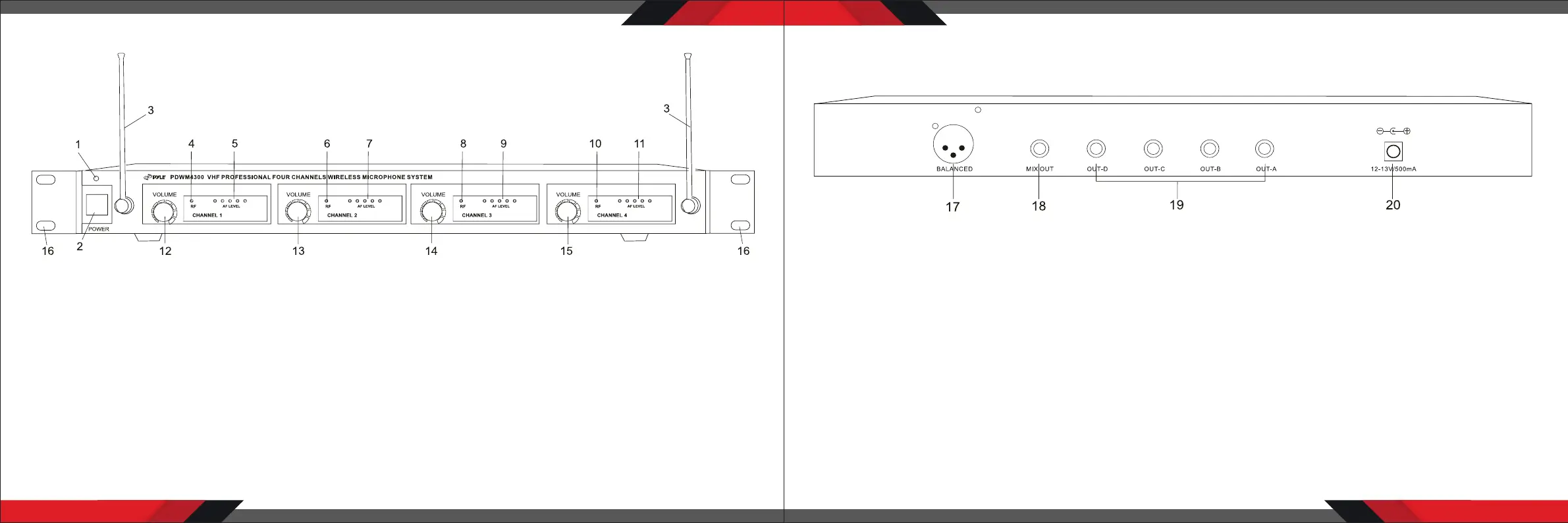
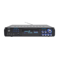
FRONT PANEL
1. Power Indicator
2. Power Switch
3. Antenna
4. CH-1 RF Signal Indicator
5. CH-1 AF Indicator
6. CH-2 RF Signal Indicator
7. CH-2 AF Indicator
8. CH-3 RF Signal Indicator
9. CH-3 AF Indicator
10. CH-4 RF Signal Indicator
11. CH-4AF Indicator
12. CH-1Volume Control
13. CH-2 Volume Control
14. CH-3 Volume Control
15. CH-4 Volume Control
16. Rack Mounts
REAR PANEL
17. Balanced Output Jack
18. Mix output Jack
19. Individual Output Jack
20. DC Power IN