www.PyleUSA.com
5
Insert your receiver / amplier’s positive (+) wires into the positive terminals, and
negative (-) wires in the negative terminals.
NOTES:
•
If your receiver / amplier has more than one set of speaker Terminal (A and B),
connect only one or the other to the Control center.
•
For the best results, we recommend 14-gauge, two conductor speaker wire
(not supplied) for most connections. If you plan to locate the speakers further
than 80 feet from the control center, use a heavier gauge of wire.
IMPEDANCE CHART
Impedance is a measurement of the load placed on your receiver/amplier
by the speakers. The load placed on your receiver/amplier from the
control center will vary depending on how many pairs of speakers you
turn on at one time, and on which speakers you turn on. The chart below
shows the impedance for all possible combinations of 8-ohm speakers.
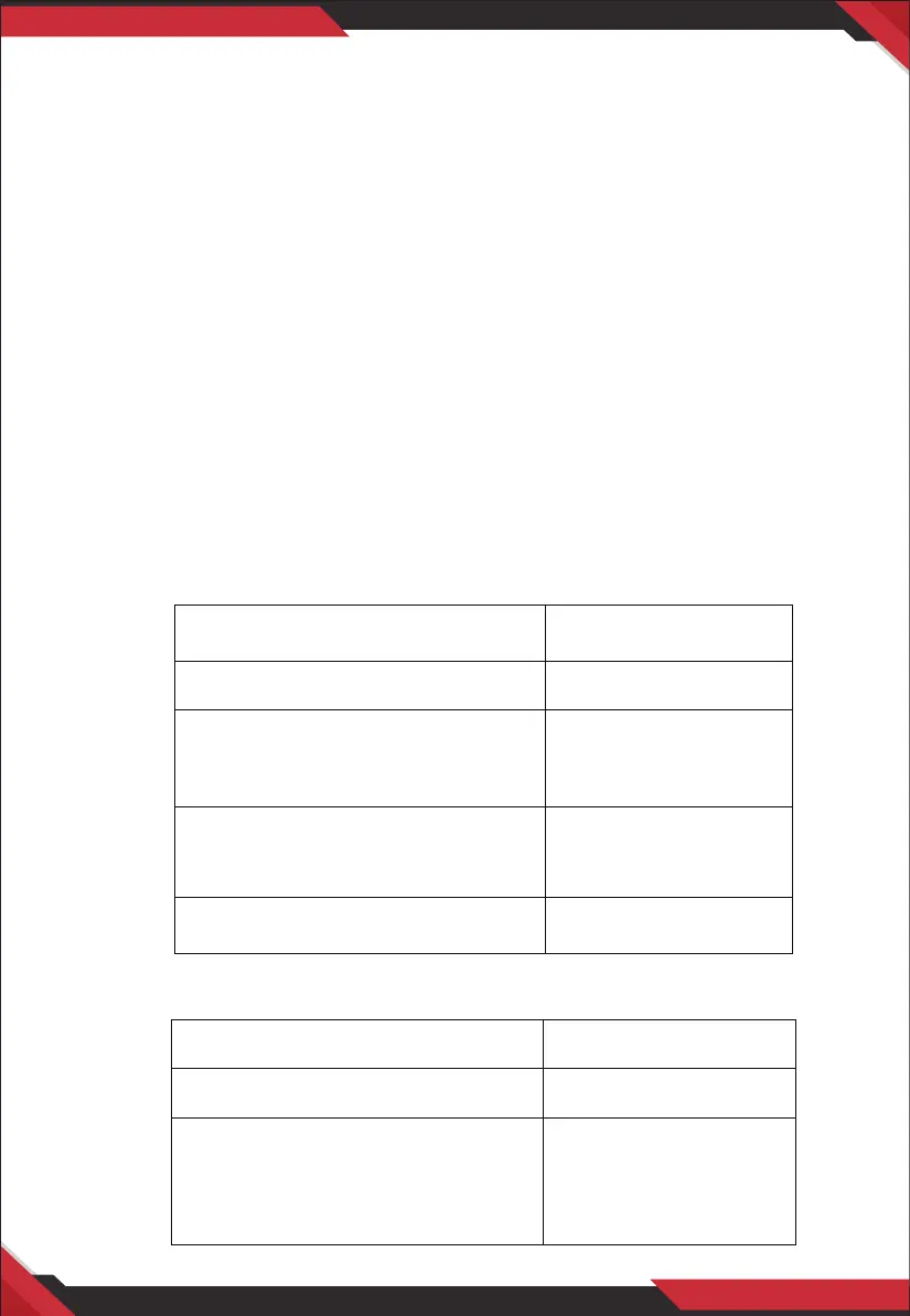
PSLSW4
PSLSW6
Speaker Sets On Impedance ()
A, B, C or D 8
A+B, A+C, A+D
B+C, B+D, C+D
4
A+B+C, A+B+D
A+C+D, B+C+D
3. 1
A+B+C+D 2. 4
Speaker Sets On Impedance ()
A, B, C, D, E or F 8
A+B, A+C, A+D
A+E, A+F, B+C
B+D, B+E, B+F
C+D, C+E, C+F, E+F
4