© 1995,1997 Directed Electronics, Inc. Vista, CA 22 97N437.597
VEHICLE RECOVERY SYSTEM
®
INSTALLATION
To install the optional VRS
®
feature, the 8618 starter kill relay must be installed. Mount the button in a well-hidden
location and plug it into the red VRS
®
port on the control unit. Make sure it cannot be pressed accidentally. The
switch must be placed where it can be reached from the driver's seat. Make sure that the customer is aware of the
location of the button and is familiar with the VRS
®
triggered sequence. This will ensure that the customer does not
become stranded by the VRS
®
.
IMPORTANT: If the VRS
®
button is being installed, you must enable the VRS
®
. Refer to
Operation Settings
Learn Routine™
section on page 18.
A few minutes are required to test the VRS
®
. To test:
Open the Owner's Guide to
Vehicle Recovery System
®
section. The triggered sequence is described
in detail.
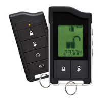
Press and release the VRS
®
push-button switch, with a door open.
Turn on the ignition and close all the doors.
Wait 15 seconds. The Status LED will begin flashing. This will be followed by chirps and flashing lights,
then by constant siren, in timed progressions described in the Owner's Guide.
The starter kill will be turned on via the orange wire: A) if the ignition is turned off after the chirps have
stopped; or B) as soon as the siren progresses to constant output.
IMPORTANT!: You must make sure that all users of the vehicle know how to disarm the VRS
®
.
Remember that the remote does not affect the VRS
®
, so make sure the user can distinguish the
standard triggered response from that of the VRS
®
.
TABLE OF ZONES
When using the diagnostic functions, use the Table of Zones to see what input has triggered the system. It is also helpful
in deciding what input to use when connecting optional sensors and switches.
Zone # Trigger Type Input Description
One Instant H1/6 BLUE wire. Connect to optional
Hood/trunk pins
Two Multiplex BLUE wire of plug-in shock sensor. Inputs
shorter than .8 seconds will trigger a Warn
Away
®
response, while inputs longer than .8
seconds will instantly trigger full alarm
sequence.
Three Two-stage, progresses from Door switch circuit. H1/5 GREEN or H1/7
warning to full alarm VIOLET.
Four Multiplex GREEN wire of plug-in shock sensor. Inputs
shorter than .8 seconds will trigger a Warn
Away
®
response, while inputs longer than .8
seconds will instantly trigger full alarm
sequence.
Five Two-stage (similar to doors) Ignition. H1/9 YELLOW.
The Warn Away
®
response does not report on the LED.