DPI SERIES USER MANUAL
6
5. Connecting the amplier
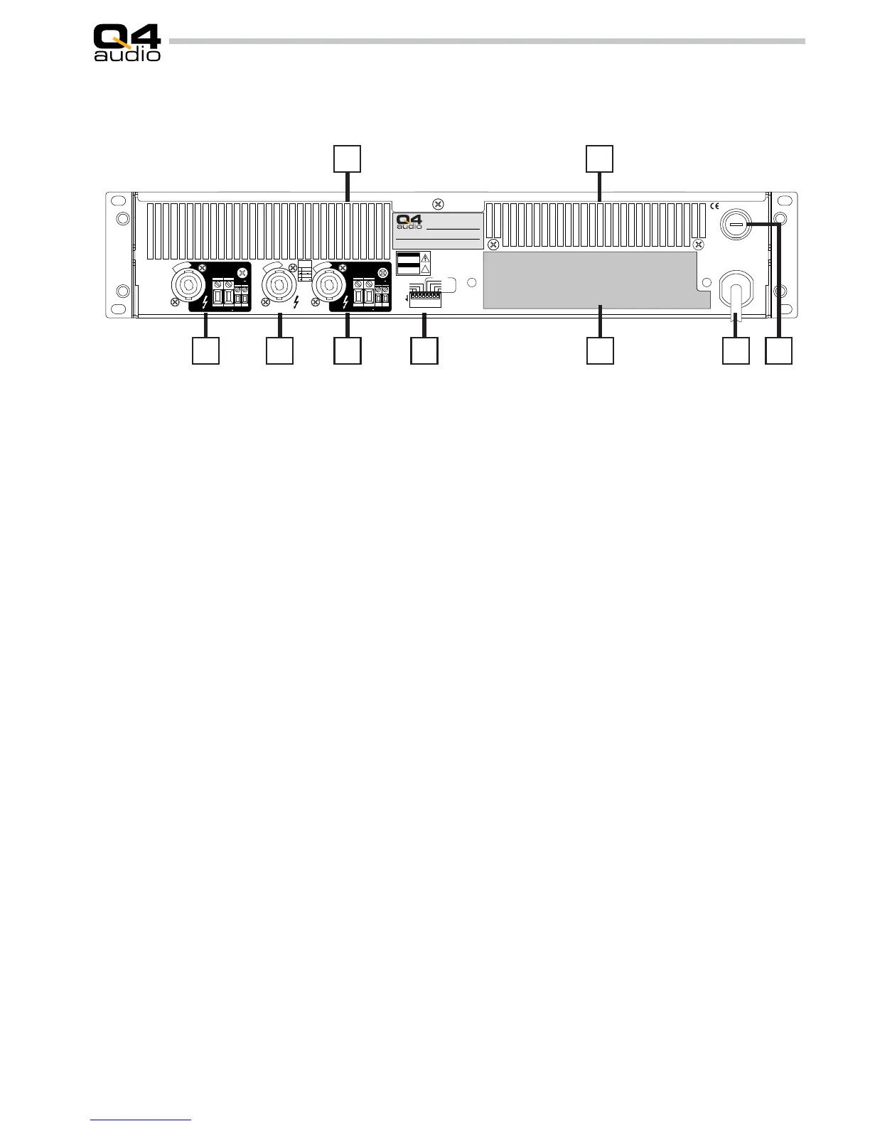
5.1 Familiarisation with the rear panel
1 Channel 1 output is available on parallel wired Neutrik 4 pole
Speakon and Phoenix screw terminal. Wiring of the Speakon
is as follows:
1+ = Channel output positive
1- = Channel output negative (ground)
2+ = Channel sense input positive
2- = Channel sense input negative (ground sense)
2 Bridge output is available on Neutrik 4 pole Speakon. Another
possibility to connect the bridge output is to use the Ch1 and
Ch2 Phoenix OUT+ terminals. In this case Ch1 OUT+ is the
positive output pole and Ch2 OUT+ the negative. Wiring is
as follows:
1+ = Bridge output positive
1- = Bridge output negative
2+ = Bridge sense input positive
2- = Bridge sense input negative
1 3 4 52 6 7
OUT+ OUT SENSE
+
CH1
OUT+ OUT SENSE
CONFIGURATION
+
CH2
WARNING:
RISK OF HAZARDOUS ENERGY!
MAKE PROPERSPEAKER CONNECTIONS - SEE
OPERATING MANUAL BEFORE USE.
MAINS FUSE
MAINS INPUT
ATTENTION:
RISQU E
D'INCENDIE! REMPL A CEZ
UNI QUEM ENT PAR UN
FUSIBLE DE MEME TYPE ET
VALEUR - CONSULTEZ LA
PLAQUE DE MARQUAGE.
WARNING:
TOREDUCE THE RISK
OF FIRE OR ELECTRIC SHOCK DO
NOT EXPOSE THIS EQUIPMENT TO
RAIN OR MOISTURE. NO USER
SERVICEABLE PARTSINSIDE.REFER
SERVICING TO QUALIFIED PERSON-
NEL. READ INSTRUCTION MANUAL
CAREFULLYBEFORE USE.
WARNING:
TOREDUCE THE RISK
OF FIRE OR ELECTRIC SHOCK DO
NOT EXPOSE THIS EQUIPMENT TO
RAIN OR MOISTURE. NO USER
SERVICEABLE PARTSINSIDE.REFER
SERVICING TO QUALIFIED PERSON-
NEL. READ INSTRUCTION MANUAL
CAREFULLYBEFORE USE.
CLASS 1 EQUIPMENT
MUST BEEARTHED!
!
AVIS
RISQUE DE CHOC
ELECTRIQUE
NE PAS OUVRIR
CAUTION
RISK OF ELECTRIC
SHOCK
DO NOT OPEN
ATTACH TYPELABEL TOTHISLOCATION. THIS
LABEL CONTAINS IMPORTANT SAFETY
INFORMATION AND MUSTNOT BE REMOVED.
REPLACE LABEL IN CASE IT GOT DAMAGED
OR LOST.
CAUTION:
FIRE HAZARD!
REPLACE ONLY WITH SAME
FUSE TYPEANDRATING- SEE
TYPE LABEL.
CH2ON/OFF
CH2SLOW
CH1ON/OFF
CH1SLOW
CH1FSMIN
CH2FSMIN
BRIDGE
L
O
C
K
L
O
C
K
L
O
C
K
CLIP LIMITER
ON
BRIDGEMODE:
SWITCHES 1 AND
2 ON USE CH1
INPUT AND LEVEL
CONTROL. CH2
INPUT AND LEVEL
BRIDGEMODE:
SWITCHES 1 AND
2 ON USE CH1
INPUT AND LEVEL
CONTROL. CH2
INPUT AND LEVEL
1+
1
2+
2
OUT
SENSE +
SENSE
OUT+
SPEAKON
WIRING
BRIDGE
1
2 3 4 5 6 7 8
Model: DPI 40
Serialnr.: DPI40-01AA-XXXX
Date of manufacture: 28.06.04
Made in Belgium, EU
FUSE: xxx A T / 250 V
Power requirments: 264V AC 50/60Hz 6.000W
8 8
3 Channel 2 output. For more information see Ch1 under point
1.
4 Conguration dipswitches.
5 Peripheral Input Module. DPI series is standard delivered
with the PIM SIM1 analog input module. Do not operate the
amplier without the module in place. The PIM module can be
easilly exchanged for versions with more elaborate features.
6 Mains power cord.
7 Fuseholder. Replace fuse only with same fuse type and
rating. This information is found on the type label, attached to
the rear panel.
8 Ventilation slots. Never cover the ventilation slots. These en-
sure reliable operation and prevent overheating of the unit.
DPI series ampliers are able to work in two main operational
modes that can be selected by the dipswitches (4) on the back
of the unit.
DUAL mode: in this mode both channels and their correspond-
ing in- and outputs work totally independent from eachother.
This is the mode for normal stereo (two-channel) operation.
In dual mode both switch 1 and 2 are in their UP position.
BRIDGE mode is activated by setting switches 1 and 2 in
the ON (down) position.
Bridge mode allows to use the ampliers full output capacity
for one single monaural channel.
This conguration is recommended to produce high power
output for a monaural speaker system, e.g. subwoofer. In ad-
dition to that, any DPI amplier working in BRIDGE mode can
be directly connected to an unisolated 100V (70V) constant
voltage sound system.
FSMIN selection: DPI series ampliers use a variable switch-
ing frequency modulator. As the output signal increases in
amplitude, the switching frequency of the modulator goes
5.2 Conguartion (dipswitch setting)
down. Ultimately the switching frequency goes to zero when
the amplier runs into the supply rails. To avoid this and to
minimise stitching of the output signal after such event, the
modulator continuously monitors the switching frequency
and clips the modulator input signal in case the switching
frequency drops below a predened value. This value can be
adjusted by the dipswitches 3 and 4 resp. for CH1 and CH2.
Switch in the UP position corresponds to 35kHz. Switch in
the down position to 70kHz. It is almost impossible to hear
any difference between both settings. We advise the 70kHz
position for critical listening. The output power will be a few
percent lower when FSMIN 70kHz is enabled, compared to
the 35kHz setting.
The CLIP LIMITER avoids gross clipping of the output signal
in case the FSMIN clipper is activated. Gain is automatically
reduced if the limiter is activated by putting switches 6 (CH2)
and 8 (CH1) in the ON (down) position. Attack and release
times can be adjusted with switches 5 (CH2) and 7 (CH1).
Reaction of the limiter circuit is slowed down by putting these
switches in their ON (down) position.
 Loading...