DPI SERIES USER MANUAL
7
The DPI series ampliers have an open input architecture
for future expansion. Standard, the amplier is equipped with
the PIM-SIM1 module.
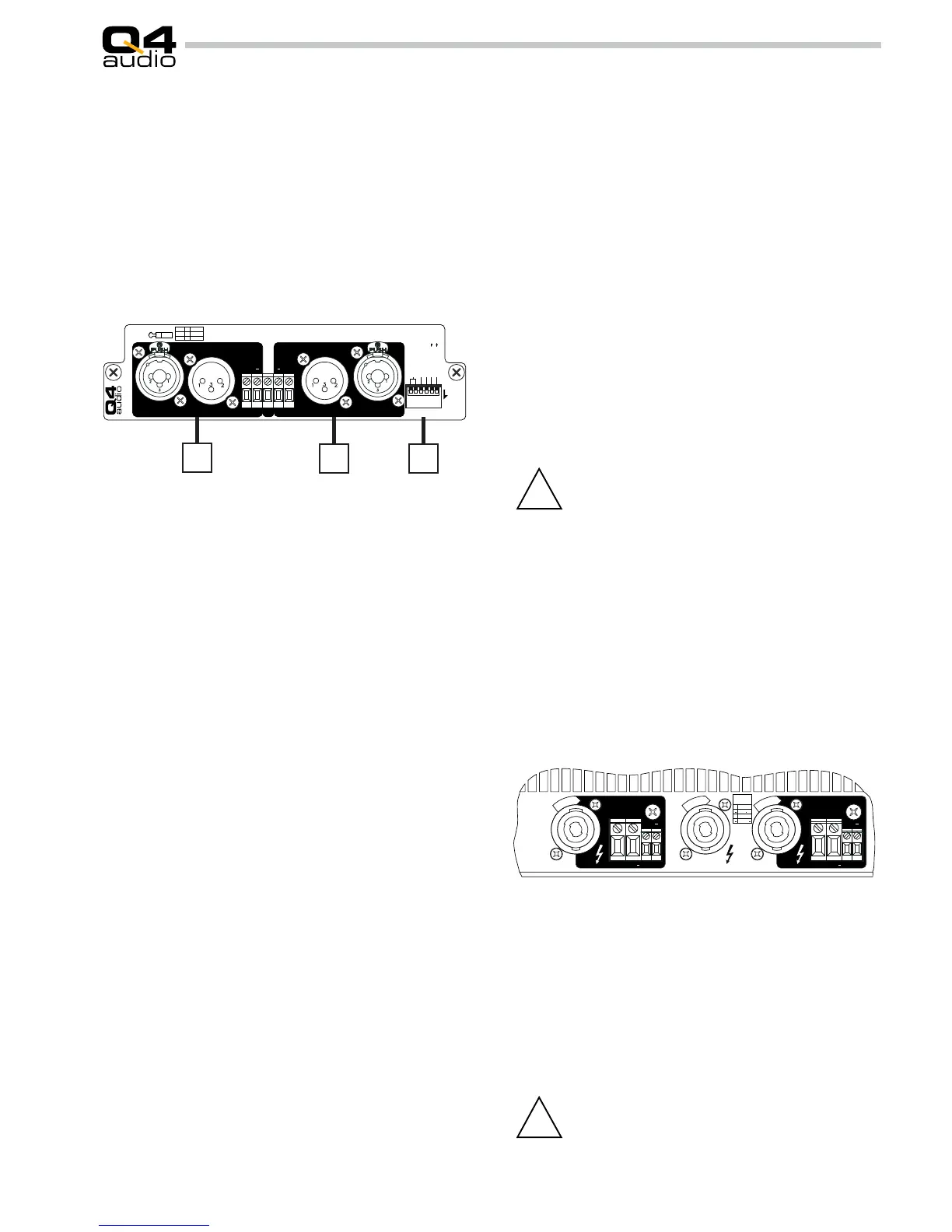
5.3.2 PIM-SIM1 module
1. Channel 1 input sockets are mixed XLR/phone jack recepta-
cles, which allow the use of microphone or instrument cables
to connect the amplier. Whenever possible, use 2-conductor
shielded cable for a balanced signal transmission. This gives
the best results and the lowest noise. The inputs are wired in
standard conguration with pin 1 as ground, pin 2 as signal
“hot” and pin 3 as signal “cold”.
Refer to the input wiring diagram on the amplier’s back
panel.
Each input XLR/Phone jack is parallel wired to a Phoenix
screw terminal for easy connections as well as to a ‘Direct Out’
male XLR socket to provide easy linking to other ampliers.
2. Channel 2 input. See Ch1 information under point 1.
All input and output sockets are on the rear panel of the
amplier. The rear panel also holds the mains cord (8) and the
fuse holder (9). For maximum safety, it is recommended to stick
to the order given below when wiring the PA system.
5.3 Connections
5.3.1 Input connections
3. Conguration dipswitches for parallel mode and high pass
lter.
Switches 1 and 2 make it possible to parallel CH1 and CH2
inputs. Put switches in the ON (down) position to wire CH1 and
CH2 inputs in parallel. Use CH1 or CH2 input. The output lev-
els can be adjusted individually by means of the corresponding
level controls.
Switch 3 makes it possible to insert a 50Hz second order high
pass lter into CH1 signal path. Put the switch in the ON (down)
position to activate the lter.
Switch 4 controls CH1 high pass lter frequency. With the
switch in the up position the cutoff frequency is 50Hz. The down
position changes this to 30Hz.
Switch 5 controls CH2 high pass lter mode and switch 6
controls CH2 high pass lter cutoff frequency. Functioning is
the same as for CH1.
Warning: All DPI series ampliers are capable of producing
dangerously high voltages at the output terminals! To avoid
cable overheating, do not use speaker cables under 1.5 mm2
cross-section (AWG 15). The use of thicker cables helps to keep
power loss down and damping high, especially if long distances
have to be bridged. After insertion, twist each speakon connector
clockwise until latching or lock it with the swivell nut to ensure
proper contact.
DUAL mode: use the SPEAKER OUT 1 and 2 outputs to con-
nect the speaker systems. Minimum total speaker impedance
per channel is 2 O hms.
BRIDGE mode: BRIDGED OUT speaker connection is done
by using standard Speakon cables. Minimum total speaker
impedance is 4 Ohms.
5.3.3 Speaker connections
EFL® (Extended Feedback Loop).
This inovating feature makes it possible to take the feed-
back for the amplier right from the loudspeaker terminals, of-
fering unprecedented control of the loudspeaker, independent
on loudspeaker cable length. The amplier can be used as a
conventional amplier without this feature enabled, without any
inconveniences by simply not connecting the sense terminals. In
this case feedback is taken right at the speaker output terminals,
compensating any internal wiring, yielding very high low output
impedance.
The sense inputs give access to highly sensitive
electronic components inside the unit.
Although the amplier is protected against mis-
wiring of the sense inputs, these components
are not resistant to continuous fault situations.
 Loading...