BWT20 Qilin double swing handheld laser
177/24
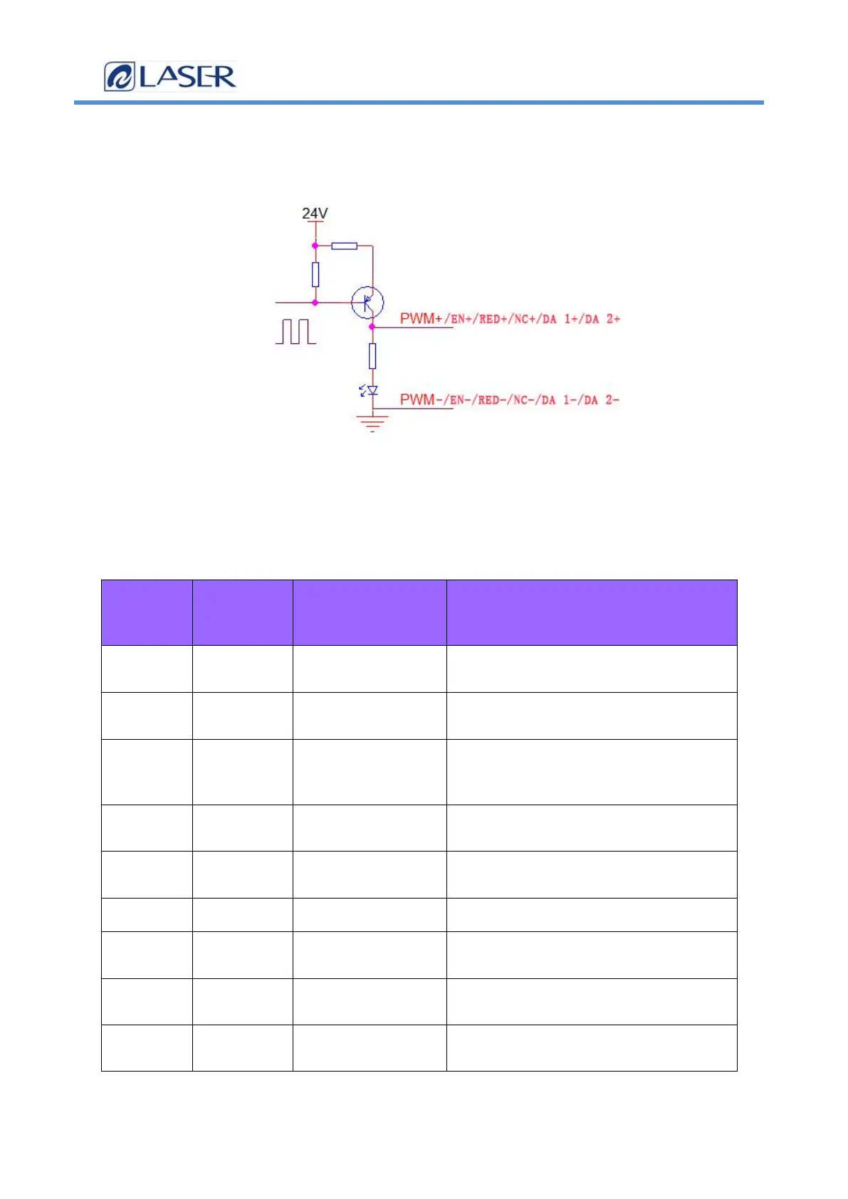
2.11 Laser control interface
The laser interface is an 8 PIN, green terminal + 4 PIN
green terminal
Figure 2.11 Schematic diagram of the laser control interface
Table 2.11 shows the definition of the laser interface.
Table 2.11
pin signal defi
niti
on
expl
ain
1 PWM+
Laser-modulated
signal +
Duty cycle 1% -100% adjustable, 24V
and 5V switchable
2 PWM- Laser Modulated
signal-
Reference to the power source
3 EN+ Laser enabling
signal +
Control laser light signal, high
level effective, 24V and 5V can be
switched
4 EN- Laser-enabling
signal-
Reference to the power source
5 RED+ Laser red light
signal
Laser red light control (optional)
6 RED- GND Reference to the power source
7 NC+ The laser enables
the backup port
Laser 24V backup port
8 NC- Laser backup port
ground
Reference to the power source
9
DA 1+ Analog voltage
output +
For laser peak power regulation, 0-
10V and 0-4V analog voltage selection