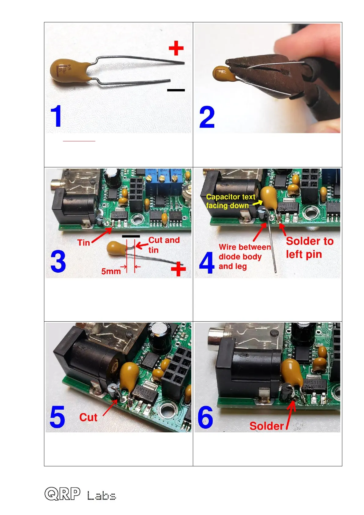
If it’s Tantalum: Any > 10uF, 16V.
Identify – and + wires (polarity is critical).
Positive is long wire, and + label on body
Straighten the wires using needle-nose
pliers or something
Cut negative wire to 5mm; tin the wire and
the left pin of the voltage regulator. This will
make them easier to solder in the next step.
The capacitor should be face (label) side
down. Pass the positive wire through next to
the diode body; solder (quickly) the negative
wire to the left pin of the voltage regulator.
Cut the positive wire right at the diode wire,
do not leave protruding wire which could
touch the enclosure wall.
Solder the positive wire to the diode wire, Be
quick… and check carefully for any short
circuits. You don’t want short circuits.
68

 Loading...