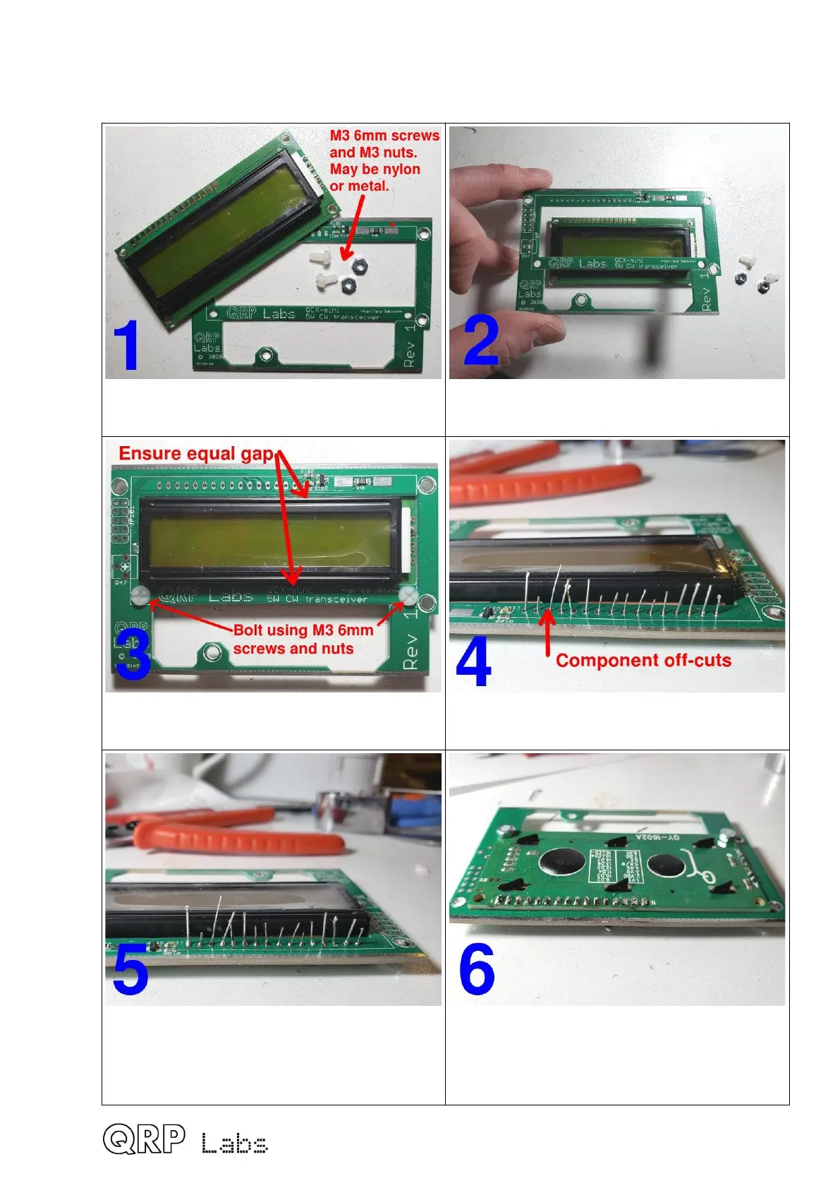
3.31 Install LCD module
Precision assembly is essential – follow the guide below carefully.
Identify the pairs of M3 6mm screws and
nuts. They may be nylon or metal.
Fit the LCD module from behind the PCB,
with its body through the rectangular cut-out
Bolt the LCD module, ensuring equal gaps
at top and bottom; tighten screws firmly.
Drop component off-cuts through the 16
holes, their bottom ends sitting on the bench
Solder the component off-cut wires to the
top of the PCB and trim (cut) the excess wire
Turn over the PCB. Ensure the LCD sits flat
on the PCB before soldering; trim excess.
Cut these wires VERY short to avoid
touching components on the main PCB later.
59

 Loading...