18
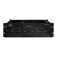
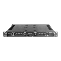
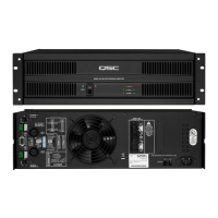
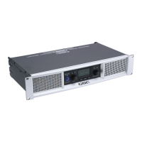
Series Three Power Amplifiers
Circuit Description
(9-1-1983)
Block Diagram
All Series Three amplifiers share the same basic circuit, with different size power supplies and different numbers of
output devices. We will use the 3500 as the basis for explanation. The circuit breaks down into the following block
diagram:
1. Power Supply, two-level main rails and op-amp rails
2. Balanced input circuit, gain control, and frequency limits
3. Amplifier feedback network, gain stage, distortion LED, and short circuit protection
4. Complementary driver transistors, crossover bias, and high/low driver sections
5. Complementary output transistors and output filters
6. Protection and signal readout circuits
7. Input/output functions (jack plane)
Detailed Explanations
Please refer to the 3500 schematic. Minor improvements made to the circuit will be explained as we go along.
1. Power Supply
AC power comes in through a thermal (slow-blow) circuit breaker and AC switch. A row of terminals on a small
circuit board allows the transformer primary to be wired for 120V, 220V, or 240V, 50-60 Hz operation, (120V only on
the 3200). There is a separate transformer for each channel, so the Series Three is a true dual-monaural design.
The transformer secondary windings are connected to the channel module through an 8-pin connector. The high-
voltage windings are rectified by B4, and filtered by E8, 9, 10 (positive) and E11, 12, 13 (negative). Half-voltage
windings are rectified by B3 and filtered by E14 (positive) and E15 (negative).
There are two unusual features of this power supply circuit. First, in addition to the usual full-voltage positive and
negative rails, we have secondary rails at half the voltage. These are used in the high-efficiency improvement
discussed in sections 4 and 5. Unlike our Series One amplifiers, the power supplies are DC-coupled with the usual
transformer center-tap. We use a speaker relay for DC protection as discussed in section 6.
The second unusual feature is that we reverse the usual location of the speaker and ground terminals. For reasons
explained in sections 4 and 5, we ground the common collectors of the output transistors, and take the audio output
from the midpoint of the power supply capacitors. This requires separate filters, rectifiers, and transformer
secondaries for each channel, but results in minimal cross talk, and permits on channel to fail without affecting the
other.
The bipolar 15V rails for the op-amp are derived using dropping resistors (R33 and R34) and zener stabilizers (Z13
and Z14) from the main rails. The op-amp supply rails are involved in our short-circuit protection scheme, as
described in section 3.
2. Balanced Input Circuit, Gain Control and Frequency Limits
The first stage of the dual op-amp is used as a differential input. Matched precision resistive dividers, R1/R3 and
R2/R4 are arranged so that any signal appearing equally on both the positive and negative inputs results in no
voltage across the op-amp input terminals and no voltage at the output of the op-amp. In other words, noise signals,
which normally occur equally on both sides of the balanced line, are rejected. The audio signal appears as a
difference between the balanced line conductors and these signals are picked up and appear at the same gain at
the output of the op-amp. For unbalanced inputs, either input line may be grounded and the circuit will respond at
unity gain to the other line. For reasons of overall stability in actual use, QSC uses the inverting input for
unbalanced signals.
After balanced-to-unbalanced conversion, the audio signal flows through R5 and C1, which roll of high frequency
response (less than -0.2dB at 20kHz, and –3dB at 200kHz). The 31-step gain control requires R6 for proper taper.
The output from the gain goes to the actual power amp circuit.