Do you have a question about the QSC PowerLight Series and is the answer not in the manual?
Illustrates graphical symbols used in the manual.
Provides critical safety warnings regarding electrical hazards and environmental exposure.
Details compliance with FCC rules for radio frequency interference.
Lists all PowerLight models covered, their size, and weight.
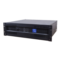
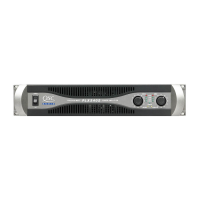
Identifies the power switch and protect, standby, and power indicator LEDs.
Describes the gain knobs and clip limiter switches for each channel.
Explains the clip, -10 dB, -20 dB, and signal LEDs for each channel.
Locates mounting holes for handles on the front panel.
Details mode switch, input barrier strip, and output terminals.
Identifies the data port and remote power supply control connector.
Locates the cooling fan and AC mains power cable connection.
Specifies checking the serial number label for correct AC mains voltage.
Explains the combo input connectors for XLR and 1/4" TRS, balanced/unbalanced.
Instructions for connecting the data port for external control or linking.
Provides guidance on speaker cable length and gauge for optimal power transfer.
Explains how to adjust the amplifier's voltage gain in dB.
Describes how to control the amplifier's power state remotely.
Explains how the clip limiter prevents continuous clipping and its effect on the audio signal.
Details the meaning of the PROTECT, STANDBY, POWER, CLIP, -10dB, -20dB, and SIGNAL LEDs.
Describes how to connect speakers for parallel, stereo, and bridged mono operation.
Provides cautions and details for operating the amplifier in bridged mono mode.
Details connecting inputs for bi-amp applications using an external crossover.
Describes connecting inputs for the single-channel mono block amplifier.
Describes amplifier muting during power transitions to prevent transients.
Explains short circuit protection and clip limiting for output safety.
Explains thermal shutdown and DC fault protection for amplifier safety.
Details input circuit isolation and ultrasonic network for stability.
Lists detailed output power ratings and distortion levels for various models.
Provides frequency response, voltage gain, and input impedance specifications.
Specifies amplifier controls, indicator LEDs, and cooling system details.
Outlines the terms and conditions of the manufacturer's warranty.
Provides mailing address, telephone numbers, and web/email contacts.
| Channels | 2 |
|---|---|
| Input Impedance | 20kΩ balanced, 10kΩ unbalanced |
| Cooling | Variable speed fan |
| Connectors | XLR, Speakon, binding posts |
| Protection | Thermal, short circuit |