EasyManua.ls Logo

QSC AD-S402T - User Manual

QSC AD-S402T
4 pages
Print Icon
To Next Page IconTo Next Page
Loading...
1
TD-001597-01-A
AD-S402T
Quick Start Guide
NOTE:
The AD-S402T is UL listed (1480A) for indoor use only
Installation
AD-S402T passive column loudspeaker systems require amplified audio signals. A pass-through on each loudspeaker permits connection to multiple loudspeakers.
The pluggable “Eurostyle” connectors allow the installer to pre-wire the audio system on site before the loudspeakers are installed.
TD-001597-01-A
*TD-001597-01*
The loudspeaker comes with a weather cover for the input cup to protect the input connections and switches from
precipitation and other weather hazards (Figure 1). Use the weather cover for all non-UL outdoor installations or any
applications where the loudspeaker may be exposed to moisture. To ensure a good seal in the cable gland, use outdoor-rated
cable with a round jacket between 5.5 mm and 9.4 mm in diameter.
To use the weather cover:
1. Loosen the nut on the cable gland.
2. Pass the cable all the way through the nut and the rest of the gland.
3. Attach the input connector to the wires (see
Input Connector
, below).
4. Once the loudspeaker enclosure is installed, plug the input connector into the loudspeaker's input cup. Secure the
connector to the loudspeaker using the two captive retaining screws, one on each end.
5. Make sure that the transformer tap selection switch is set properly.
6. Place the cover onto the loudspeaker's input cup and attach it using the four screws, lock washers, and flat washers
provided.
7. Dress the cable so there is no undue strain on it. Tighten the gland nut until the grommet inside the gland has made a
tight seal onto the cable jacket.
Input Connector
AD-S402T Weather Cover
Diameter
up to
0.37 in
9.4 mm
— Figure 1 –
Strip wire
¼in
6.3 mm
Up to
10 AWG
6 mm²
Turn screw fully
counterclockwise.
Insert wire fully.
Turn screw clockwise
to clamp wire tightly.
— Figure 2 –
INPUT
THRU
To other
loudspeaker(s),
if necessary
— Figure 3 –
The pluggable “Eurostyle” input connector (Figure 2) has four terminals to facilitate connection on a distributed
line. It also allows the installer to pre-wire the venue before the loudspeakers themselves are installed. The
connector accommodates wire up to 10 AWG or 6 mm
2
. Be sure of proper and consistent polarity at each connector
(Figure 3). If one or more loudspeakers is out of polarity with others, the acoustic performance will suffer. Always
secure the connector to the loudspeaker using the retaining screws at both ends.
Mounting
Tilt/Swivel Bracket
The bracket provided with the loudspeaker allows 0, 5,
10, 15, and 20 degrees of downward tilt (Figure 4), and
up to ±55 degrees of horizontal panning (Figure 5).
These angles may be constrained by the loudspeaker
enclosure and adjacent walls or other structural elements.
In addition, the bracket can be inverted, which allows the
loudspeaker to be tilted up.
— Figure 4 –
120 degrees pan
at 0 degrees tilt
— Figure 5 –
Question and Answer IconNeed help?

Do you have a question about the QSC AD-S402T and is the answer not in the manual?

Overview

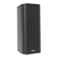
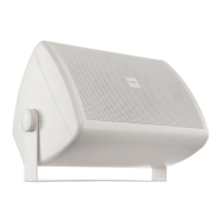
The AD-S402T is a passive column loudspeaker system designed for indoor use, with UL listing (1480A). It requires amplified audio signals and features a pass-through connection for linking multiple loudspeakers. The system utilizes pluggable "Eurostyle" connectors, allowing installers to pre-wire the audio system on-site before the loudspeakers are installed.

Weather Cover:

The loudspeaker includes a weather cover for the input cup, protecting connections and switches from precipitation and other weather hazards. This cover is recommended for all non-UL outdoor installations or any applications where the loudspeaker may be exposed to moisture. For a secure seal, outdoor-rated cable with a round jacket between 5.5 mm and 9.4 mm in diameter should be used.

Weather Cover Usage:

  1. Loosen the nut on the cable gland.
  2. Pass the cable through the nut and the rest of the gland.
  3. Attach the input connector to the wires.
  4. Once the loudspeaker enclosure is installed, plug the input connector into the loudspeaker's input cup and secure it with the two captive retaining screws.
  5. Ensure the transformer tap selection switch is set correctly.
  6. Place the cover onto the input cup and attach it using the four screws, lock washers, and flat washers provided.
  7. Dress the cable to avoid undue strain and tighten the gland nut until a tight seal is made onto the cable jacket.

Input Connector:

The pluggable "Eurostyle" input connector features four terminals for distributed line connections. It accommodates wire up to 10 AWG or 6 mm². Proper and consistent polarity is crucial for optimal acoustic performance. The connector is secured to the loudspeaker with retaining screws at both ends.

Power Selection:

A selector switch in the input cup allows users to choose the desired power for the loudspeaker or bypass the transformer for a low impedance load. The switch supports both 70-volt and 100-volt lines. After power selection, the weather cover should be installed.

Mounting - Tilt/Swivel Bracket:

The provided bracket allows for 0, 5, 10, 15, and 20 degrees of downward tilt, and up to ±55 degrees of horizontal panning. These angles may be limited by the enclosure, adjacent walls, or other structural elements. The bracket can be inverted to allow upward tilting. For mounting without panning, a zero-pan locking screw is included.

The AD-S402T has three attachment locations for the bracket, with center points measured from the bottom edge of the enclosure. Two M6 x 20 screws with flat washers are used to attach the bracket to the rear panel. Inverting the bracket offers additional configurations, allowing the loudspeaker to be tilted up. An M6 eyebolt is included for attaching a safety tether, as required by building codes.

Maximum Pan Range (AD-S402T):

Bracket Position 0° tilt 5° tilt 10° tilt 15° tilt 20° tilt Tilt bracket removed
1 ±55° ±55° ±55° ±54° ±54° N/A
2 ±55° ±54° ±53° ±51° ±49° ±50°
3 ±55° ±51° ±46° ±40° ±32° ±50°
4 (1 inverted) ±55° ±45° ±29° ±7° N/A N/A
5 (2 inverted) ±55° ±46° ±33° ±15° N/A N/A
6 (3 inverted) ±55° ±50° ±43° ±33° ±22° ±50°

Attaching the Wall Piece:

The wall piece is attached to the wall or other mounting surface. A full-size template is provided for accurate placement. Consultation with a structural engineer is recommended for selecting mounting locations and fasteners.

Attaching the Loudspeaker Bracket Pieces (Tilting):

  1. Select the appropriate attachment location on the enclosure's rear panel. Lower attachment locations generally offer a wider range of tilt options.
  2. Use two M6x20 screws and washers to secure the bracket to the enclosure. The bracket has four mounting holes, with some locations using long-spaced holes and others using shorter ones.
  3. It is recommended to configure the tilt angle before attaching the loudspeaker and bracket to the wall piece, though adjustments can be made later.
  4. Continue to "Attaching the loudspeaker to the wall piece."

Attaching the Loudspeaker Bracket Pieces (No-Tilt Mounting):

For applications not requiring tilting, the mounting bracket can be simplified:

  1. Omit certain parts of the bracket kit.
  2. Attach the remaining part of the bracket directly to the loudspeaker enclosure using two M6 × 20 screws.
  3. Continue to "Attaching the loudspeaker to the wall piece."

Attaching the Loudspeaker to the Wall Piece:

  1. Align the hole in the loudspeaker bracket piece over the stud on the top of the wall piece, and guide the loudspeaker bracket's bottom stud through the hole in the wall piece.
  2. Set the loudspeaker onto the wall piece.
  3. Install a washer and cap nut on each stud and tighten them finger tight.
  4. Adjust the horizontal pan of the loudspeaker as needed.
  5. If the desired horizontal angle is perpendicular to the wall, install the zero-pan locking screw. Ensure the threaded hole in the loudspeaker bracket piece aligns with the hole in the wall piece, then insert and tighten the screw.
  6. Tighten the cap nuts securely.

Horizontal Suspension:

The loudspeaker can also be suspended horizontally, facing down. Two M6 eyebolts are installed into the holes at each end of the rear panel. One clear finish eyebolt is included; additional eyebolts are available from QSC Technical Services Group (part # HW-000323-01). Each suspension line and the structural member must be adequately rated according to local codes. A structural engineer should be consulted for guidance.

Safety Warnings:

  • Always read and follow instructions carefully to prevent personal injury and damage.
  • Consult a professional mechanical or structural engineer licensed in the jurisdiction for review, verification, and approval of all attachments to the building or structure.
  • Employ a professional rigger for hoisting, positioning, and attaching equipment.
  • Use all suspension hardware and components correctly.
  • Calculate suspended loads and ensure they do not exceed component limits.
  • Comply with local codes and regulations for suspended loads.
  • Use only appropriate M6 eyebolts for suspension.
  • Verify the integrity of all structural members supporting suspended loads.
  • Never assume owner- or third-party-supplied attachment points are adequate.
  • Before lifting, inspect all components (enclosures, brackets, pins, frames, bolts, nuts, slings, shackles, etc.) for cracks, wear, deformation, corrosion, and missing, loose, or damaged parts. Discard and replace worn, defective, or suspect parts with new, appropriately load-rated parts.

Shock Loading:

Moving or stopping a load magnifies its static weight, and sudden actions can greatly increase this magnification, known as shock loading, which can be dangerous. Shock loading can be instantaneous or gradual and undetected until visible damage or failure occurs. Precautions include careful planning, understanding equipment suspension requirements, and proper lifting practices. Natural forces (winds, earthquakes) can also impose shock loads several times greater than the static load. Therefore, structures and suspension equipment must always be rated at several times the weight of the suspended equipment.

QSC AD-S402T Specifications

General IconGeneral
BrandQSC
ModelAD-S402T
CategorySpeakers
LanguageEnglish

Related product manuals