8
TD-001571-01-B
I
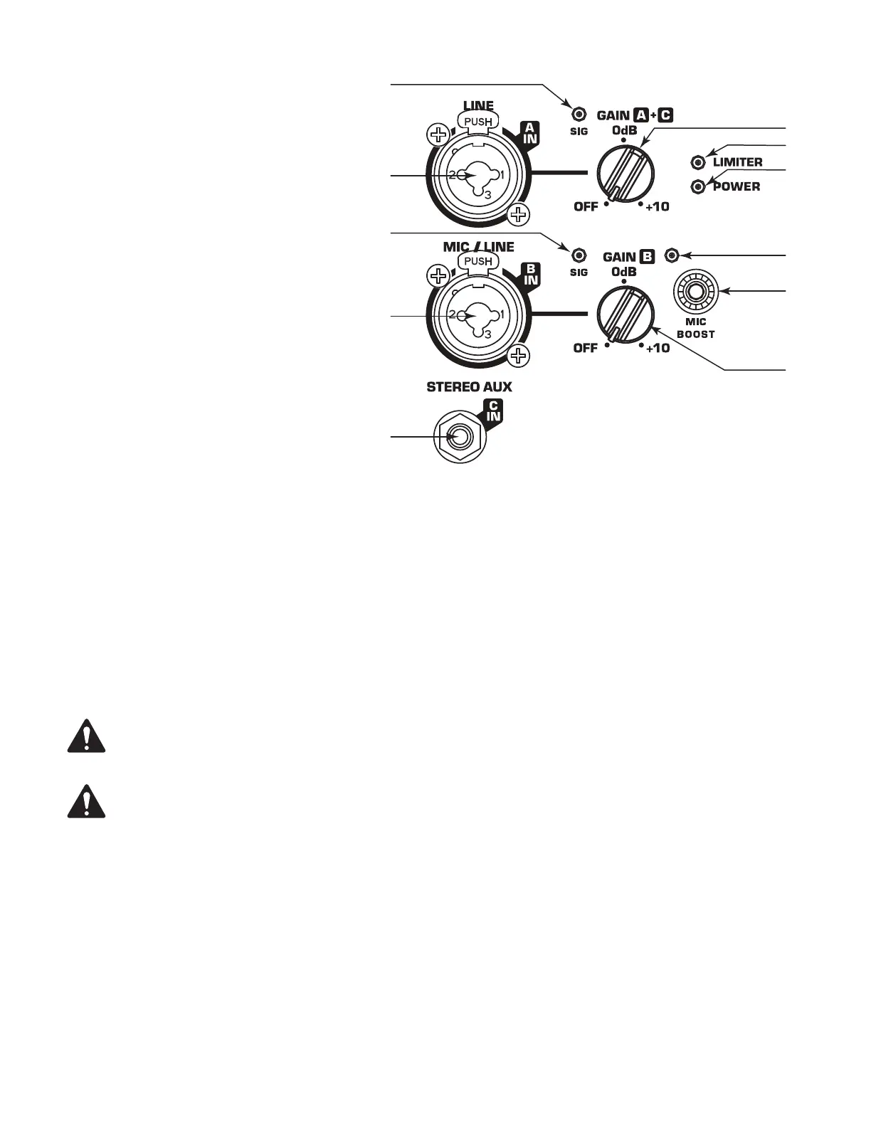
The CP Series amplifier has three separate inputs; two
combination XLR/1/4 inch TRS (Inputs A and B) and
one 1/8 inch (3.5 mm) TRS (Input C).
Refer to Figure 9
1. Input A SIG LED – When illuminated (green), it
indicates a signal is present. If this LED is not
illuminated, the input signal is missing or too low
to detect.
2. Input A – Combination XLR – 1/4 inch TRS
connector. Balanced XLR and 1/4 inch input.
Accepts line-level inputs.
3. Input B SIG LED – When illuminated (green), it
indicates a signal is present. If this LED is not
illuminated, the input signal is missing or too low
to detect.
4. Input B – Combination XLR – 1/4 inch TRS
connector. Balanced XLR and 1/4 inch input.
Accepts line-level and mic-levelinputs.
5. Input C Stereo 1/8 inch (3.5 mm) TRS connector
– Accepts line-level stereo input. Stereo input
received at Input C is summed to mono.
6. Input A + C GAIN knob – Sets the gain of Input A and Input C that controls the signal level sent to the amplifier and the MIX OUT (POST
GAIN) output.
7. LIMITER LED – Illuminates (red) when the built-in limiter is activated to avoid damage to the amplifier or loudspeaker. If the signal level
at any frequency is too high, or the amplifier is too hot, the limiter is activated and the LEDisilluminated.
8. POWER LED – Illuminates (green) when power is applied to the unit and the ON/OFF switch is in the ON position.
9. MIC BOOST LED – When illuminated (yellow) it indicates the input is configured to provide a +25 dB boost for microphones requiring a
higher input gain. When not illuminated, it indicates the input is configured for a line-level input including microphones that provide a
standard line-level output. The MIC BOOST setting should only be used if a microphone is connected directly to the MIC/LINE input.
NOTE: The MIC/LINE input does not provide phantom power.
CAUTION! The MIC BOOST setting should only be used if a microphone is connected directly to the MIC/LINE input. Using
the MIC BOOST setting for line-level may introduce distortion. Use caution when changing to the MIC BOOST selection as the
output level increases significantly when MIC BOOST is selected.
10. MIC BOOST button – Switches between MIC BOOST level input and line-level input. When engaged, MIC BOOST LED is illuminated, and
MIC BOOST level (+25 dB) is selected for Input B. When disengaged, line-level is set for Input B.
11. Input B GAIN knob – Sets the gain of Input B that controls the signal level sent to the amplifier and the MIX OUT (POST GAIN) output.
— Figure 9 —
7
6
8
9
11
 Loading...