5
EN
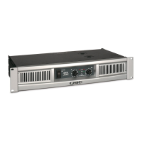
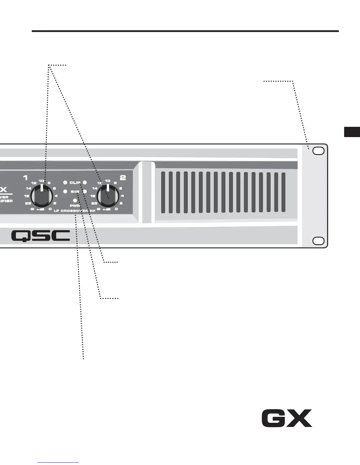
GAIN CONTROLS, CH1, CH2
The markings show attenuation in dB. For normal
use, keep the control in the upper half of its range
(less than 10 dB of attenuation). If set below half,
the source may overload before the amplifi er
reaches full power.
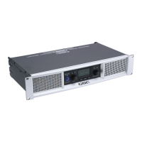
RACK MOUNTING
Fits standard 19-inch rack, 2RU.
Accepts #10 or 6 mm screws,
as determined by the rack rails.
Add rear support to prevent
damage in portable rigs.
RED CLIP LEDS
Red fl ashing indicates the amp is being overdriven. Heavy overdrive triggers internal gain
reduction, to reduce overload distortion. Normal gain will resume after the signal level returns to
normal. See Troubleshooting if the red LED remains on continuously.
GREEN SIGNAL LEDS
The green LED starts fl ashing on soft signals (-35 dB), and changes to steady green as the
signal level increases.
BLUE POWER LED
The blue PWR (POWER) LED indicates that the AC switch is on, and the amp is receiving
power. Within two seconds, it is ready to use.
ALTERNATE GAIN MARKING
When the CROSSOVER switch is active (see rear panel),
LF (CH 1) controls low frequencies (subwoofer),
HF (CH 2) controls the high frequencies (mid-high box).
 Loading...