4
TD-000351-00-E
EN
Connect the Loudspeakers
WARNING!:
When the AC power is on, there can be potentially dangerous voltage at the output
terminals on the rear of the amplifier. Be careful not to touch these contacts. Turn off the AC mains
disconnect switch before making any connections.
1. Turn off the AC mains power switch on the back of the amplifier.
2. Wire the loudspeaker cables to male NL4 connectors (Figure 8) as needed for your amplifier's configuration. Refer to
Table 1 for details.
3. Plug the cables into the appropriate chassis NL4 connectors on the rear of the amplifier. Refer to Figure 5 through
Figure 7 for connection diagrams.
The following table shows you which pins on which output you can use for each mode. Where there is more than one connector for a given mode,
the PLD allows you to use one, all, or some of the available connectors. For example, in ABCD Parallel mode, you can use pins 1+ and 1- of outputs
A through D in any combination; the pins of all the outputs are in parallel and electrically the same. It is recommended that where the pins are
electrically the same, you use all available pins whether by jumpers between pins, or direct wiring to each loudspeaker
Mode
NL4 Separate AB Parallel ABC Parallel ABCD Parallel
A
Ch A 1+ / 1-
1+ / 1- 1+ / 1- 1+ / 1-
Ch B 2+ / 2-
1
B
1+ / 1- 1+ / 1- 1+ / 1- 1+ / 1-
CD Parallel
C
Ch C 1+ / 1-
1+ / 1- 1+ / 1- 1+ / 1-
Ch D 2+ / 2-
1
D
1+ / 1- 1+ / 1- 1+ / 1-
A+B Bridged C+D Bridged AB+CD Bridged
X
1+ / 1- 2+ / 2-
1
1+ / 1-
Y
1+ / 1-
— Table 1 —
1 For Bi-Amp operation.
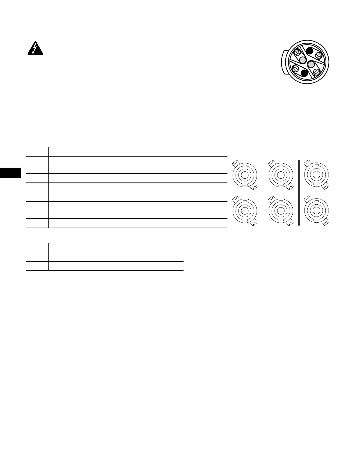
— Figure 8 —
1+
1-
2-
2+
Male NL4 Wiring
— Figure 9 —
A
C
B
D
X
Y
Standard Bridged
Output Connectors