7
EN
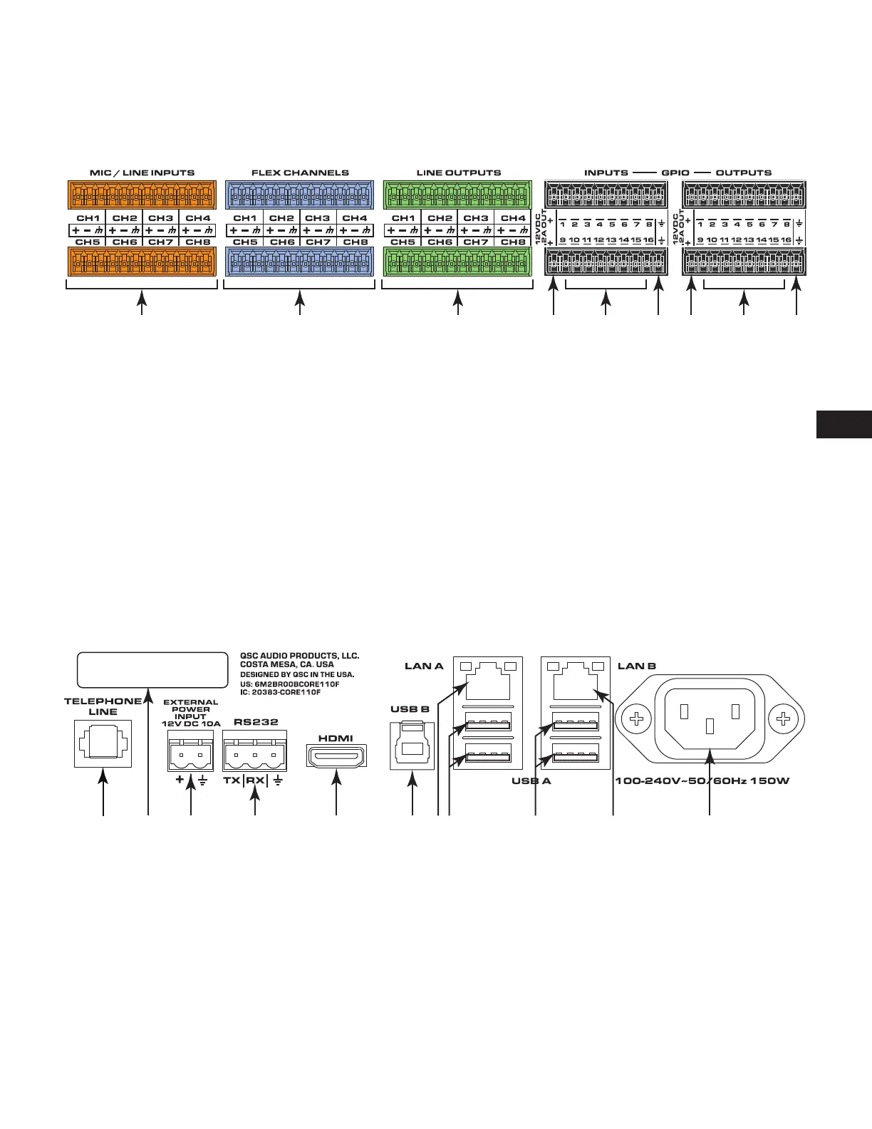
Rear Panel (left side)
All audio inputs and outputs use one 3-position, 3.5mm Euro connector for each channel. GPIO uses one 10-position 3.5mm Euro connector for
eachrow (not applicable to the Core 110f v2).
All inputs and outputs are configured in Q-SYS Designer Software.
— Figure 3 —
1 2 3 4 5 4 76 6
1. Mic/Line Inputs – eight channels, balanced or unbalanced,
phantom power – orange
2. Flex Channels – eight user-configurable input/output
channels, balanced or unbalanced, phantom power on
inputs – blue
3. Mic/Line Outputs – eight channels, balanced or unbalanced
- green
The following connections use the black Euro plug and are not
applicable to the Core 110f v2:
4. 12VDC, 0.2A Outputs + uses connector pins 1 and 11
(notnumbered)
5. General-purpose Inputs – 16 inputs, 0-24V analog input, or
contact closure (Pins labeled 1–16 equal pins 1–16 in the
Q-SYS Designer GPIO Input component)
6. Earth ground – uses pins 10 and 20 (not numbered)
7. General-purpose Outputs – 16 outputs, open collector
(24V, 0.2A maximum) with pull up to +3.3V (Pins labeled
1–16 equal pins 1–16 in the Q-SYS Designer GPIO Output
component)
— Figure 4 —
SN/ 1212121212121212
1 3 4 5 6 98 107 82
1. Telephone Line – RJ11 (6P2C)
2. Serial Number of the Core 110
3. External Power Input – Auxiliary power, 12VDC, 10A, 2-pin,
5 mm Euro connector.
4. RS232 – Transmit and receive, 3-pin, 5 mm, Euro connector
5. HDMI – for future use
6. USB Type B Device connector
7. LAN A – Q-LAN, control, VoIP, WAN streaming, AES67 etc.,
RJ45
8. USB Type A Host connectors (4)
9. LAN-B – Redundancy, control, VoIP, etc.
10. A/C Power Input – IEC connector, 100-240V ~ 50-60 Hz,
150W, universal power supply
 Loading...