9
EN
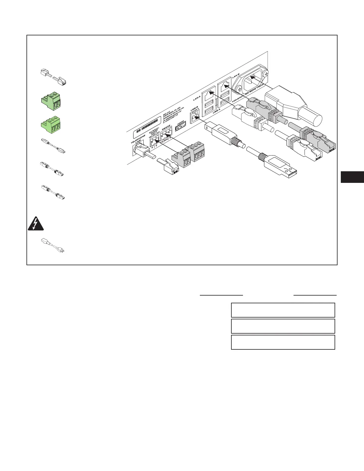
Core 110 Series Communication and Power Connectors
Make the following connections as
required. Refer to Figure 9.
1.
Telephone Cable,
RJ12,6-Conductor
2. 2-pin Euro
connector – for
+12VDC 10A
3. 3-pin Euro
connector – for
RS232 TX and RX
4. USB Type B – for
external devices,
not supplied
5. RJ45/Cat5E –
audio, & control,
not supplied
6. RJ45/CAT5E –
audio, & control,
redundant network,
not supplied
WARNING!: The AC Mains plug, is the AC mains disconnect device and shall remain readily accessible after
installation.
7. AC Mains – The Core 110 Series has a Universal power supply 100 – 240 VAC, 50 – 60 Hz, with an IEC
connector.
— Figure 9 —
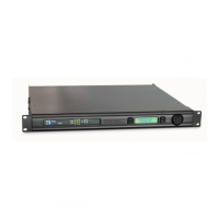
Front Panel OLED Screens
(Not applicable to the Core 110f v2)
Design Status
Refer to Figure 10
• Device – The name of the Core as defined in Q-SYS Designer.
• Design – The name of the currently running design.
• Status –
◦ OK – Audio is good, hardware is good.
◦ Compromised – Audio is good but a redundancy mechanism is active (one LAN down but the other is still up) or a non-fatal
hardware problem exists (fans too slow, temperature higher than expected, etc.)
◦ Fault – Audio is not passing, or hardware is malfunctioning or mis-configured
◦ Missing – A piece of hardware, defined in the design, has not been discovered. Audio is not passing through that piece of
hardware.
◦ Initializing – Starting the firmware, configuration update, and the design. Audio is obviously bad.
◦ Not Present – A virtual component in the design, that is designated as Dynamically Paired, and Not Required, has no hardware
assigned to it.
— Figure 10 —
DEVICE:
DESIGN:
STATUS:
DESIGN STATUS
<Core Name>
<Design Name>
<Status>
 Loading...