4 QSC, LLC
Using Q-SYS with Dolby® Atmos
Using design blocks for Atmos
Enabling the cinema library in the first step gave you access
to cinema-specific components and devices such as the
Atmos Receiver.
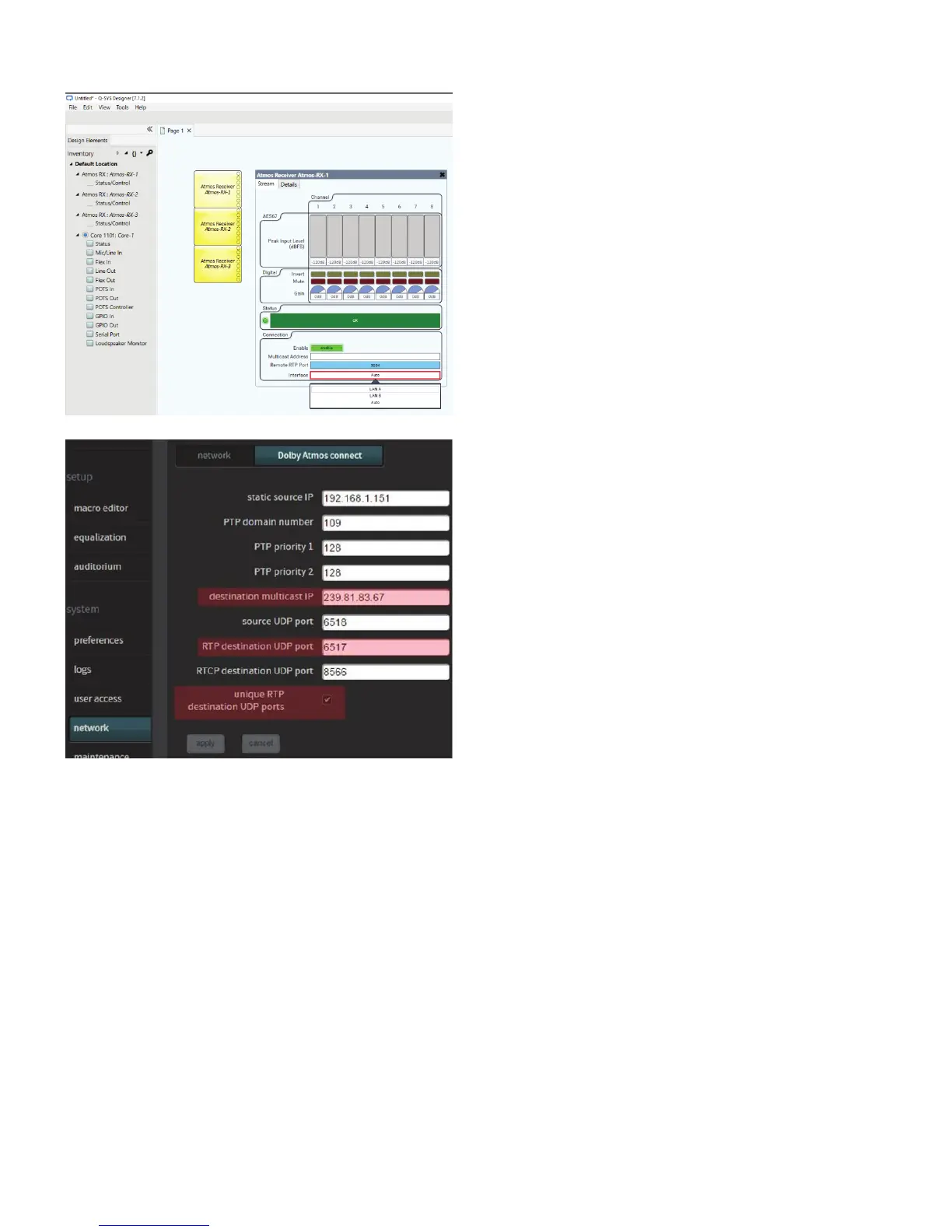
1. Add Atmos Receiver blocks to the design as needed.
Each block has eight outputs available.
2. Double-click each Atmos Receiver block to open its
interface window.
3. With the design running (either Save To Core & Run or
Emulate), set each block to Enable. Set each to a unique
Remote RTP Port as assigned by the Dolby CP850
processor or IMS3000 server.
4. Set each block’s Interface to LAN A.
Dolby CP850 and IMS3000 settings
1. Open a web browser and enter the IP address of the
Dolby CP850 processor in the address bar. Set up the
browser and Q-SYS Designer Software windows side-by-
side so you can match the settings between them.
2. Log into the server’s web interface. Select Dolby Atmos
connect.
Notes:
• The static source IP needs no modification. It is used by
Dolby.
• The PTP domain number must match that of the desti-
nation core processor but differ from the PTP domains of
the other core processors.
• Acceptable values for PTPv2 priorities are 1 through 253.
(For more information, see https://www.luminex.be/
improve-your-timekeeping-with-ptpv2/.)
• The destination multicast IP address here and in the
Q-SYS core processor must match. The Q-SYS default
is 239.81.83.67, but it can be changed in the Atmos
Receiver block in Q-SYS Designer Software, if necessary.
• The RTP destination UDP port must match the
Remote RTP Port number in the first Atmos Receiver
block. The port number in each successive additional
Atmos Receiver block must increment by 1. Q-SYS
defaults to these values, but you should check them to
confirm.
3. In Dolby Atmos connect, select unique RTP destina-
tion UDP ports and click apply.
NOTE: Make sure you have Dolby Atmos and AES67 enablement licenses or keys in the CP850 or IMS3000. These are
installed or enabled through a Key Delivery Message (KDM). Contact Dolby for information.
 Loading...