EasyManua.ls Logo

QSC SPA2-60 User Manual

QSC SPA2-60
12 pages
To Next Page IconTo Next Page
Page #1 background imageLoading...
Page #1 background image
System Power Amplifier (SPA)
Installation Guide
SPA2-60 Amplifi er
SPA4-60 Amplifi er
EXPLANATION OF SYMBOLS
The term “WARNING!” indicates instructions regarding personal safety. If the instructions are not followed the result may be bodily injury or death.
The term “CAUTION!” indicates instructions regarding possible damage to physical equipment. If these instructions are not followed, it may result in
damage to the equipment that may not be covered under the warranty.
The term “IMPORTANT!” indicates instructions or information that are vital to the successful completion of the procedure.
The term "NOTE" is used to indicate additional useful information.
The intent of the lightning fl ash with arrowhead symbol in a triangle is to alert the user to the presence of un-insulated "dangerous"
voltage within the product's enclosure that may be of suffi cient magnitude to constitute a risk of electric shock to humans.
The intent of the exclamation point within an equilateral triangle is to alert the user to the presence of important safety, and operating
and maintenance instructions in this manual.
What's in the Box
(1x)
(1x)
(2x)
(2x)
(2x)
(6x)
(6x)
(4x)
(1x) SPA2-60 (1x)
SPA4-60 (2x)
SPA2-60 (1x)
SPA2-60 (1x)
SPA4-60 (1x) SPA4-60 (1x)
(1x)
Warranty TD-000453
(1x)
Safety Information TD-000337
TD-000500-01 -A
*TD-000500-01 *
Question and Answer IconNeed help?

Do you have a question about the QSC SPA2-60 and is the answer not in the manual?

QSC SPA2-60 Specifications

General IconGeneral
BrandQSC
ModelSPA2-60
CategoryAmplifier
LanguageEnglish

Summary

Installation

Ventilation

Ensures proper airflow and heat dissipation for safe operation and prevents output power reduction.

Rack-Mounting Options

All Configurations

Guidelines for mounting amplifiers in various rack configurations using provided or optional hardware.

Front Panel

Front Panel Indicators

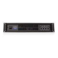
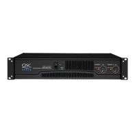
Description of status indicators on the front panel including Power, Signal, and Limiter/Protect.

Rear Panel

Rear Panel Connections and Controls

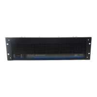
Overview of rear panel connectors, switches, and controls for amplifier configuration and connectivity.

Connections

Wire Preparation for Connections

Instructions for stripping wire to the correct length and avoiding tinning for secure terminal connections.

Output Connectors

Details on connecting speaker outputs using the specified Euro connectors for SPA2-60 and SPA4-60 models.

Input Connectors

Guide to connecting audio inputs using Euro connectors for both SPA2-60 and SPA4-60 amplifiers.

Balanced and Unbalanced Inputs

Input Signal Wiring

Diagrams illustrating how to connect balanced and unbalanced audio sources to the amplifier inputs.

Stereo Mode

Stereo Mode Configuration

Explanation and diagrams for configuring the amplifier for 8 Ohm or 4 Ohm stereo operation.

4 or 8-ohm Bridged Mode

Bridged Mode Wiring

Instructions for connecting speakers in 4 or 8 Ohm bridged mode for higher power output.

70V / 100V Bridge Mode

70V/100V Bridged Operation

Details on setting up the amplifier for high-impedance 70V or 100V distributed audio systems.

Remote Control

Remote Level and Standby Control

Explanation of using 3.5mm connectors for remote volume control and standby function.

Specifications

Related product manuals