6
TD-000500 -01 -A
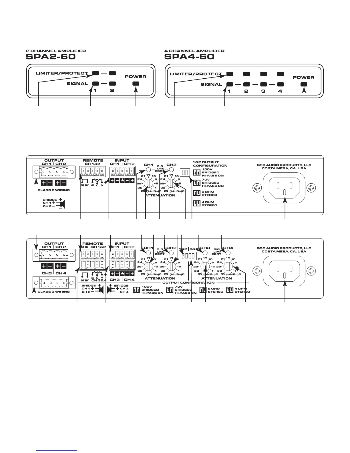
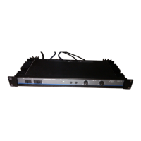
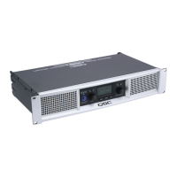
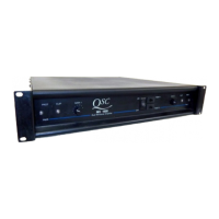
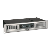
Front Panel
— Figure 9 —
Limiter / Protect
Red – Protect / Mute
Orange – Limiter on
Input Signal
Blue – Present
Power
Blue – On
Orange – Standby
Limiter / Protect
Red – Protect / Mute
Orange – Limiter on
Input Signal
Blue – Present
Power
Blue – On
Orange – Standby
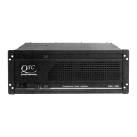
Rear Panel
— Figure 10 —
12345467 8
8
12345467
91011 121314
44
1. Output Channels 1 & 2
2. Remote Control Channels 1 & 2
3. Input Channels 1 & 2
4. Channel 1 thru Channel 4 Status LEDs
a. Green – Normal Signal Level
b. Amber – Input or Output Overload/
Clipping or Thermal Limiting
c. Red – Limit or Protect Mode
d. Red – Thermal Limit or Protect Mode
e. Red – Mute
1
5. Channel 1 Attenuator Control
6. Channel 2 Attenuator Control
7. Mode Confi guration Switches Channel 1& 2
8. AC Power Connection
9. Output Channels 3 & 4
10. Remote Control Channel 3 & 4
11. Input Channels 3 & 4
12. Mode Confi guration Switches Channel 3 & 4
13. Channel 3 Attenuator Control
14. Channel 4 Attenuator Control
1 No signal for 10 minutes, amplifi er outputs are muted (LEDs are red). No signal for 25 minutes, amplifi er is put in Standby Mode (Rear LEDs are off).