Do you have a question about the QSC ISA 450 and is the answer not in the manual?
Explains safety symbols and warnings for safe operation and shock prevention.
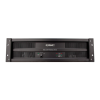
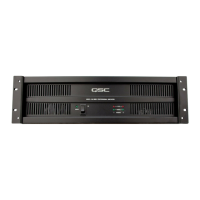
Details how to operate the amplifier's power switch and its associated LED indicator.
Explains the meaning of the Power, Signal, and Clip LEDs for monitoring amplifier status.
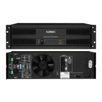
Explains the function of the DataPort V2 connector for accessory interfacing and monitoring.
How to configure and use the amplifier in stereo mode for separate channel operation.
How to configure and use the amplifier in parallel mode to drive both channels from one input.
Explains bridge mono mode for delivering higher power to a single load.
Details the DIP switch configurations required for bridge mode operation.
Explains the purpose of the clip limiter and its benefits for speaker protection.
Details how to enable or disable the clip limiter using DIP switches for each channel.
How to connect speakers to the low impedance outputs in stereo, parallel, and bridge modes.
Warnings and restrictions for using 2-ohm loads in bridge mode and high voltage wiring.
Guides for connecting to distributed audio lines (25V, 70V, 100V) in stereo/parallel modes.
Guides for connecting to distributed audio lines (140V, 200V) in bridge mode.
Steps to diagnose and resolve issues when the power LED is not illuminated.
Troubleshooting steps for when signal LEDs are not responding or responding incorrectly.
Diagnosing short circuits or load issues indicated by the flashing clip LED.
Interpreting a steady clip LED indicating protective muting due to overheating or overload.
Diagnosing causes of distorted audio, including low impedance loads and clipping.
Identifying incorrect mode switch settings or mono sources causing lack of channel separation.
Troubleshooting steps for addressing hiss and hum noise from input signals or grounding.