EasyManua.ls Logo

QSC CX-Q Series User Manual

QSC CX-Q Series
25 pages
To Next Page IconTo Next Page
Page #1 background imageLoading...
Page #1 background image
TD-001586-01-B
*TD-001586-01*
CX-Q & CX-Q
Q-SYS Network Amplifiers
User Manual
CX-Q 2K4 — 4 Channel, 2000 W Network Amplifier with Mic/Line Inputs
CX-Q 4K4 — 4 Channel, 4000 W Network Amplifier with Mic/Line Inputs
CX-Q 8K4 — 4 Channel, 8000 W Network Amplifier with Mic/Line Inputs
CX-Q 4K8 — 8 Channel, 4000 W Network Amplifier with Mic/Line Inputs
CX-Q 8K8 — 8 Channel, 8000 W Network Amplifier with Mic/Line Inputs
CX-Qn 2K4 — 4 Channel, 2000 W Network Amplifier
CX-Qn 4K4 — 4 Channel, 4000 W Network Amplifier
CX-Qn 8K4 — 4 Channel, 8000 W Network Amplifier
CX-Qn 4K8 — 8 Channel, 4000 W Network Amplifier
CX-Qn 8K8 — 8 Channel, 8000 W Network Amplifier
®
Question and Answer IconNeed help?

Do you have a question about the QSC CX-Q Series and is the answer not in the manual?

QSC CX-Q Series Specifications

General IconGeneral
DanteYes
THD+N<0.05%
DSPYes
WeightVaries by model
Power OutputVaries by model
Frequency Response20Hz - 20kHz (+0/-0.5dB)
Power per channel (8 ohms)Varies by model
Power per channel (4 ohms)Varies by model
Power per channel (2 ohms)Varies by model
Bridged ModeYes
Height2U
ProtectionThermal, short circuit, DC, overload

Summary

Explanation of Symbols

Important Safety Instructions

Maintenance and Repair

FCC Statement

Environmental Specifications

RoHS Statement

Warranty Information

What's in the Box

Features Overview

Amplifier Front Panel

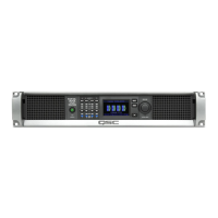
Overview of controls and indicators on the front of the amplifier.

Amplifier Rear Panel

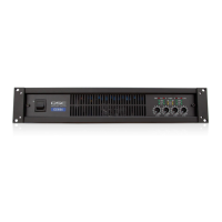
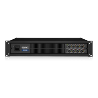
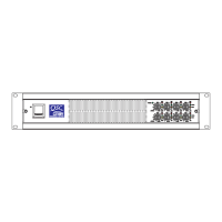
Details of connectors and ports on the rear of the amplifier.

Installation and Wiring

Rack-Mount the Amplifier

Guidance on securely mounting the amplifier in a standard rack.

Wire Preparation Guidelines

Instructions for preparing input and output wiring for amplifier connections.

Input and Output Connectivity

Analog Input Connections

How to connect analog audio sources to the amplifier inputs.

GPIO Connectivity

Information on connecting General Purpose Input/Output pins for control.

Output Configuration Overview

Setting up amplifier output channels for various loudspeaker configurations.

Loudspeaker Connection Procedures

AC Mains Connection

AC Power Connection Procedure

Procedure for connecting the amplifier to the AC power source.

Amplifier Controls and Indicators

Amplifier Modes and Buttons

Explanation of amplifier operational modes and front panel buttons.

Front Panel Controls Overview

Details on gain adjustment, selection, ID, and reset functions.

Input and Output Signal Flow

CX-Q Series Signal Flow

Diagram and explanation of audio signal path for CX-Q amplifiers.

CX-QN Series Signal Flow

Diagram and explanation of audio signal path for CX-QN amplifiers.

On-Screen Display Information

STATUS Screen Details

Information on the amplifier's operational status and firmware.

LAN and HEALTH Screens

Details on network settings and system health monitoring displays.

Output Gain and Status Screens

Standalone Output Gains Screen

Overview and adjustment of output gains without Q-SYS design.

Output Status Indicators

Explanation of LEDs indicating DAC, PROTECT, LIMIT, and SHORT conditions.

Channel Configuration and Input Status

Channel Configuration Screens

Visual representation of amplifier output channel configurations.

Routable Mic/Line Inputs Status

Monitoring input levels, mute status, and clipping for mic/line inputs.

GPIO Pinout and Applications

Specifications

Power Specifications – 4-Channel Models

Detailed power output ratings for 4-channel amplifier models.

Power Specifications – 8-Channel Models

Detailed power output ratings for 8-channel amplifier models.

Peak Voltage Specifications

Peak voltage and current capabilities for amplifier channels across models.

Operating Specifications

Heat Loss and Current-Draw Charts

Current Consumption Data

Related product manuals