16
TD-001586-01-B
GPIO
There are 16 General Purpose Input Output pins for use in various applications.
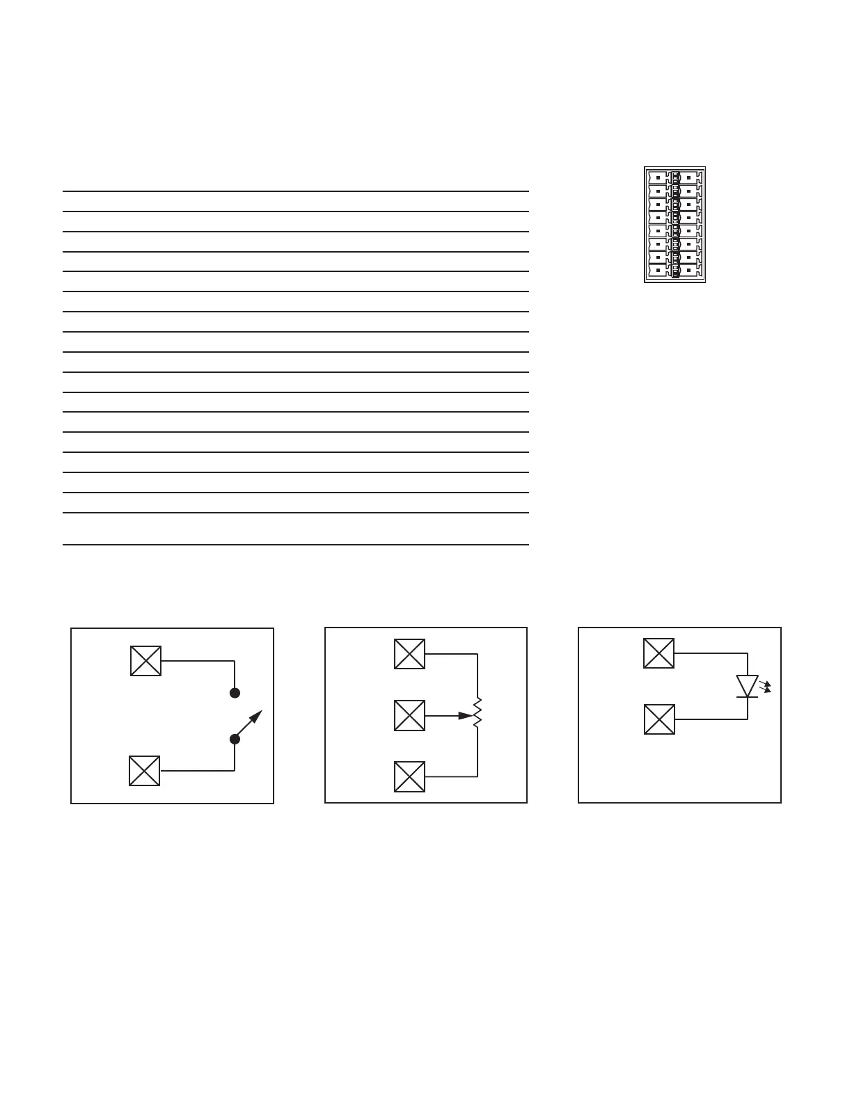
Figure 23 shows the pin configuration for the connector on the
rear of the amplifier. — Table 2 shows the connector pin-out. Figure 24 gives some simple GPIO applications.
— Table 2 —
Connector Pin GPIO # and
Function
Specifications
1 3.3 V 100 mA max (power cycle to reset current limiting)
2 GPIO 1 5mA in/out, 3.3V max, 127Ω resistor in series
3 GPIO 2 5mA in/out, 3.3V max, 127Ω resistor in series
4 GND Ground
5 GPIO 3 5mA in/out, 3.3V max, 127Ω resistor in series
6 GPIO 4 5mA in/out, 3.3V max, 127Ω resistor in series
7 GND Ground
8 GPIO 5 18mA in/out max, 3.3V max, 127Ω resistor in series
9 RELAY NO
1
Relay Normally Open
10 RELAY COM
1
Relay Common
11 RELAY NC
1
Relay Normally Closed
12 GND Ground
13 GPIO 6 18mA in/out max, 3.3V max, 127Ω resistor in series
14 GPIO 7 18mA in/out max, 3.3V max, 127Ω resistor in series
15 GND Ground
16 GPIO 8 18mA in/out max, 3.3V max, 127Ω resistor in series
1 Nominal switching capacity is 30 VDC at 2 A for a total of 60 W maximum. The maximum
voltage is 220 VDC if the current is limited to observe the maximum power rating (60 W).
Examples
Button or Contact Closure Potentiometer Q-SYS-Powered LED
— Figure 24 —
GPIO
Ground
+3.3 V
GPIO
Analog In
Ground
GPIO 5-8
Ground
Works for LEDs up to 18 mA.
Current is limited in the GPIO
circuit by a 127Ω resistor in series.
— Figure 23 —
1
2
3
4
5
6
7
8
9
10
11
12
13
14
15
16
 Loading...