13
TD-001586-01-B
Screens
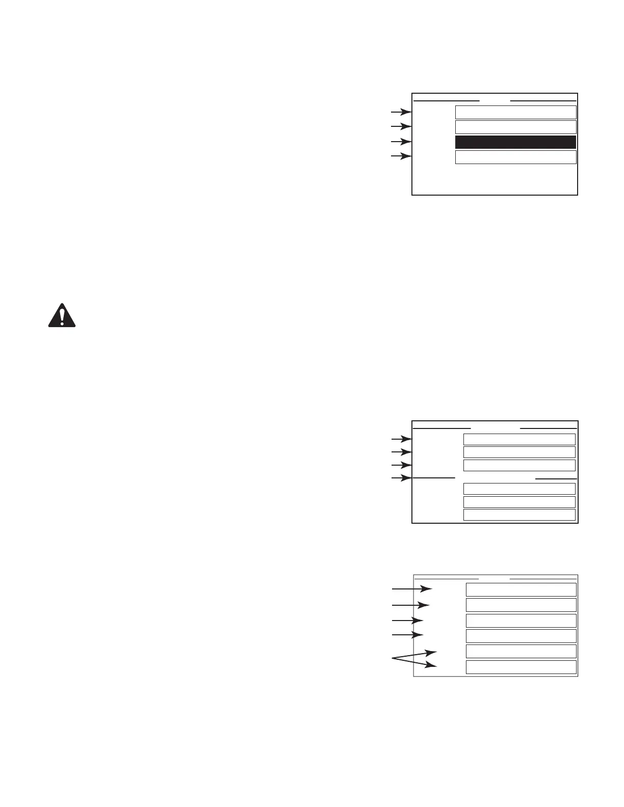
STATUS Screen
Refer to
Figure 16
1. DEVICE – the hostname (network name) of the amplifier. A default name is
given at the factory, similar to the example. You may change the name in the
Q-SYS Configurator.
2. DESIGN – the name of the Q-SYS design currently running on the amplifier. The
amplifier must be contained in a running design tooperate.
3. STATUS – displays the current status of the amplifier both in text and color. The
following is a list of possible status colors, and some example conditions.
• OK – green – audio is good, hardware is good.
• Compromised – orange – audio is good but a redundancy mechanism is active (one
LAN down but the other is still up) or a non-fatal hardware problem exists (fan speed, high
temperature, low AC voltage, output load, amplifier is in Protect mode, etc.)
• Fault – red – audio is not passing, or hardware is malfunctioning or mis-configured (amplifier power off, audio streams broken, amplifier fault,
loudspeaker short circuit, etc.)
• Initializing – blue – In the process of initialization, and design start. Audio cannot pass.
4. FIRMWARE – the Q-SYS Designer firmware version installed on the amplifier.
NOTE: The CX-Q 4- and 8-channel amplifiers require Version 8.1.0 or later of Q-SYS Designer.
To Update the Amplifier Firmware:
a. Install the version of Q-SYS Designer you want to use on your PC.
b. The amplifier must be connected to Q-LAN and turned on.
c. Open the Q-SYS design containing the amplifier in the Designer version you just installed.
d. Select "Save to Core and Run" from the File menu.
e. The amplifier and any other Q-SYS peripherals in the design are automatically updated.
LAN A / LAN B Screen
Refer to
Figure 17
1. IP ADDRESS – a default address is assigned in the factory. You can change this
and the other parameters in Q-SYS Configurator. LAN A is required, and cannot be
turned off.
2. NETMASK – must be the same as the Core's Netmask.
3. GATEWAY – must be the same as the Core's Gateway.
4. LAN B is not required. When connected, the same type of information as LAN A is displayed.
HEALTH Screen
Refer to
Figure 18
1. FAN RPM – varies depending on the temperature.
2. PSU TEMP – varies depending on operating conditions. PSU Temp is monitored
and can automatically put the amp into limiting or shutdown if safe operating
temperatures are exceeded.
3. AC VOLTAGE – AC Mains voltage
4. AC CURRENT – AC mains current drawn by the amplifier.
5. Voltage Rails
• V RAIL 1 = +147VDC +/- 5V typical
• V RAIL 2 = -147VDC +/- 5V typical
— Figure 16 —
STATUS
DEVICE: CXDQ8CH-1234
DESIGN: My Design Filename
STATUS: OK
FIRMWARE:
CX-Q
8.1.0
— Figure 17 —
LAN B (AUTO, NO LINK)
GATEWAY:
NETMASK:
255.255.0.0
IP ADDRESS:
192.168.xxx.xxx
GATEWAY:
NETMASK:
IP ADDRESS:
LAN A (AUTO)
1
2
3
4
— Figure 18 —
FAN RPM:
2443
PSU TEMP: 30.0°C
AC VOLTAGE: 114V
AC CURRENT: 1.58A
V RAIL 1: 149V
V RAIL 2: -149V
1
3
5
2
4
 Loading...