EasyManua.ls Logo

QSC CXD Series User Manual

QSC CXD Series
78 pages
To Next Page IconTo Next Page
Page #1 background imageLoading...
Page #1 background image
CXD Amplifier
Quick Start Guide
EXPLANATION OF TERMS AND SYMBOLS
The term “WARNING!” indicates instructions regarding personal safety. If the instructions are not followed the result may be bodily injury or death.
The term “CAUTION!” indicates instructions regarding possible damage to physical equipment. If these instructions are not followed, it may result in
damage to the equipment that may not be covered under the warranty.
The term “IMPORTANT!” indicates instructions or information that are vital to the successful completion of the procedure.
The term "NOTE" is used to indicate additional useful information.
The lightning flash with arrowhead symbol in a triangle is to alert the user to the presence of un-insulated "dangerous" voltage within
the product's enclosure that may be of sufficient magnitude to constitute a risk of electric shock to humans.
The exclamation point within an equilateral triangle is to alert the user to the presence of important safety, and operating and
maintenance instructions in this manual.
NOTE:
This Quick Start Guide is based on the basic configuration as the amplifier comes from the factory: four separate inputs
and four separate outputs. For detailed instructions for custom configurations refer to the CXD User Guide (TD-000367).
Installation
The following steps are written in the recommended installation order.
Rack-Mount the Amplifier
The CXD Series amplifiers are designed to mount in a standard rack-mount unit. The amplifiers are 2RU high. The CXD4.3 and CXD4.5 are 381 mm (15
in) deep, while the CXD4.2 is 229 mm (9 in) deep.
1. Secure the amplifier in the rack with eight screws (not supplied)—four in front and four in back. For complete instructions, refer to TD-000050 Rear
Rack Ears Installation Guide, which can be found on the QSC website (www.qsc.com)
CAUTION!:
Be sure that nothing blocks the front or rear ventilation openings and that each side has a clearance of at least
2 cm.
AC Mains
WARNING!:
When the AC power is on, there may be potentially dangerous voltage
at the output terminals. Be careful not to touch these contacts. Turn off the AC mains
disconnect switch prior to making any connections.
1.
Make sure the power switch on the rear of the amplifier is off.
2. Connect the IEC power cord to the AC receptacle. (Figure 1)
WARNING!:
Do not turn the amplifier on yet.
— Figure 1 —
TD-000350-00-E
*TD-000350-00*

Other manuals for QSC CXD Series

Question and Answer IconNeed help?

Do you have a question about the QSC CXD Series and is the answer not in the manual?

QSC CXD Series Specifications

General IconGeneral
Amplifier ClassClass D
Channels4
Input TypeAnalog
DSPYes
Form FactorRack-mountable
Load Compatibility4Ω, 8Ω
Input ConnectorsXLR
ProtectionShort circuit, thermal overload, DC fault
Frequency Response20 Hz - 20 kHz, ±0.2 dB
Output ConnectorsSpeakon NL4

Summary

Understanding Terms and Symbols

Explanation of Terms

Defines safety terms like WARNING, CAUTION, IMPORTANT, and NOTE.

Safety Symbols

Explains the lightning flash and exclamation point safety symbols.

Installation

Rack-Mounting the Amplifier

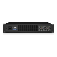
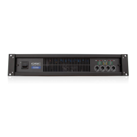
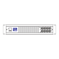
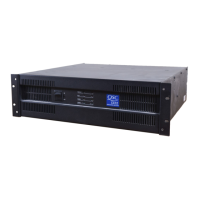
Instructions for physically mounting the amplifier in a rack unit.

AC Mains Connection

Details on connecting the amplifier to the AC power source.

Inputs

Audio Input Connections

Describes how to connect balanced and unbalanced audio sources.

Outputs

Output Overview

Explains the four configurable outputs and their capabilities.

Separate Channel Wiring

Details wiring for four separate loudspeakers.

Output Configurations

Bridged and Separate Channels

Instructions for bridging channels or using separate channels for loudspeakers.

Parallel Channel Wiring

Explains wiring for one or multiple loudspeakers using parallel configuration.

Connecting Loudspeakers

Loudspeaker Connection Procedure

Provides safety warnings and steps for connecting loudspeakers.

Amplifier Control Interface

Front Panel Controls Overview

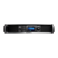
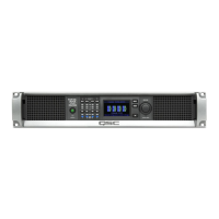
Introduces the front panel controls, including buttons, LEDs, and the master control knob.

Button and LED Functionality

Details the functionality of buttons and the meaning of LED indicators.

Amplifier Power Modes

Describes the amplifier's Off, Run, Standby, and Mute All operational modes.

Amplifier Operation and Navigation

Signal Flow and Menu Tree

Illustrates the signal path and outlines the amplifier's menu system.

AC Power On Sequence

Steps for safely powering on the amplifier after connecting loudspeakers.

Preset Management

Screen Types

Describes the different types of screens: Informational, Navigational, and Parameter Editing.

Understanding and Creating Presets

Explains presets and details how to create and manage user-defined presets.

Preset Wizard

Preset Wizard Introduction

Introduces the Preset Wizard for simplifying preset creation and configuration.

Wizard Configuration Steps

Guides through setting impedance, power, and assigning speakers in the wizard.

Speaker and Preset Configuration

Speaker Type and Settings

Details selecting speaker models, band, and filter settings for each channel.

User Preset Number and Naming

Guides on selecting a user preset number and creating a custom name.

Modifying and Saving Presets

Recalling and Modifying Presets

Explains how to recall presets to modify amplifier configurations.

Saving and Overwriting Presets

Explains saving current settings and using the SAVE AS feature.

Utilities

Utilities Overview

Introduces the Utilities section for accessing amplifier information and functionality.

Related product manuals