EasyManua.ls Logo

QSC CX168 User Manual

QSC CX168
36 pages
To Next Page IconTo Next Page
Page #1 background imageLoading...
Page #1 background image
1
User Manual
CX168
8-Channel Installed Sound
Professional Audio Amplifier
TD-000095-00 rev.A
*TD-000095-00*
Question and Answer IconNeed help?

Do you have a question about the QSC CX168 and is the answer not in the manual?

QSC CX168 Specifications

General IconGeneral
TypePower Amplifier
Channels8
Signal-to-Noise Ratio> 100 dB
Input Sensitivity1.4 V
Damping Factor> 200
Frequency Response20 Hz - 20 kHz
CoolingVariable speed fan
Height3.5"
Width19"
Input ConnectorsXLR, 1/4 in TRS
Output ConnectorsBinding Post, Speakon
Input Impedance20 kΩ

Summary

Important Safety Precautions & Explanation of Symbols

Introduction

Front Panel

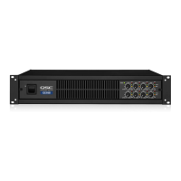
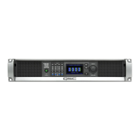
Overview of the amplifier's front panel controls and indicators.

Rear Panel

Dimensions and Mounting Points

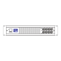
Detailed physical dimensions and rack mounting specifications.

Installation: Unpacking & Rack Mounting

Installation: Cooling & AC Mains Requirements

AC Mains Connection

Proper procedures for connecting the amplifier to AC power.

Setup: Setting the Mode Configuration DIP Switches

Setup: Stereo, Parallel, or Bridge Modes

Stereo Mode

Configuration for stereo operation with separate channels.

Parallel Mode

Configuration for parallel operation using a single input signal.

Bridge Mode

Configuration for bridge mode to combine channels for higher power.

Setup: Clip Limiter and Low Frequency Filters

Clip Limiter

Explanation and usage of the channel clip limiters.

Low Frequency Filter

Explanation and usage of the low frequency filters.

Low Frequency Filtering Tips

Connections: Using the Terminal Block Inputs

Connections: Using the DataPorts

How to Connect to the DataPort

Procedure for connecting accessories to DataPort.

Connections: Outputs

Stereo and Parallel Mode Outputs

Wiring instructions for stereo and parallel speaker connections.

Bridge Mode Outputs

Wiring instructions for bridge mode speaker connections.

Connections: Using the Terminal Block Outputs

Operation: Power Switch and Gain Controls

Power Switch

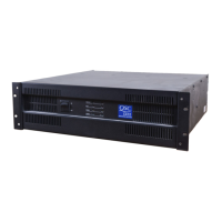
Instructions for operating the power switch and its indicator.

Operation: LED Indicators

Operation: Gain Controls

Operation: Gain Control Security Plate

Operation: Using the QSC DataPort Connections

DataPort Connectors

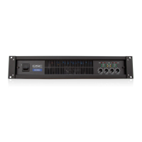
Description of the DataPort connectors and their function.

Troubleshooting: No Sound

Troubleshooting: Distortion, No Channel Separation, Hum, Hiss, Feedback

Distorted Sound

Diagnosing and resolving distorted audio output.

Specifications

Amplifier Protection

Details on the amplifier's protection circuitry.

Related product manuals