12
TD-001586-01-B
Input and Output Signal Flow
CX-Q Series Amplifiers
Refer to
Figure 14
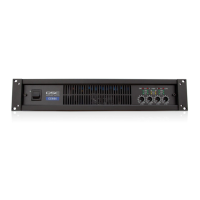
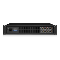
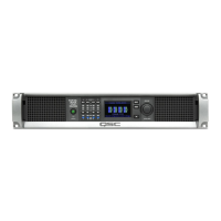
The CX-Q 4K8 and CX-Q 8K8 amplifiers have eight MIC/LINE inputs and eight (two blocks of four) amplified outputs on the rear of the amplifier. The
CX-Q 2K4, CX-Q 4K4, and CX-Q 8K4 amplifiers have four MIC/LINE inputs and four (one block of four) amplified outputs on the rear of the amplifier.
The inputs and outputs are not physically (or electrically) connected in the amplifier giving you the flexibility to use any available source in Q-SYS for
the amplified outputs, and to route the inputs to any output. The inputs and outputs can be connected in your Q-SYS design as shown in
Figure 14
.
1. The analog inputs are converted to digital audio in the amplifier
2. The converted audio is then routed to the Q-SYS Core via Q-LAN (LAN A, LAN B).
3. The digital signals are brought into the design via the amplifier's Mic/Line Input component.
4. From the Mic/Line Input component the signals can be sent for processing and can be sent anywhere within the Q-SYS system.
5. In the Q-SYS Core digital audio signals (not necessarily from the amp's inputs) are sent to the Q-SYS Amp Output component.
6. The digital audio is then sent from the Q-SYS Core via Q-LAN to the amplifier.
7. Digital signals are converted to analog, amplified and sent to outputs of the amplifier.
— Figure 14 —
ROUTABLE INPUTS
21 43
65 87
MIC/LINE
12V Phantom
Q-LAN
Q-LAN
Q-SYS Core
8-Channel Model Shown
Amplifier
Rear Panel
Outputs
QSC
Loudspeakers
Mic/Line
Input CX-Q
Amp
Output
Amplifier-1
CX-Q
Q-SYS
DSP
Routing
Amplifier
Rear Panel
Inputs
The Q-SYS Amp Output component can have one to eight inputs/outputs depending on the amplifier model and its configuration in Q-SYS Designer.
The desired configuration is selected in the Q-SYS Designer Properties menu for the amplifier. When the amplifier's configuration is changed, all
of the outputs are placed in a "mute all" state. You can un-mute all by clicking the Mute All button in Q-SYS Designer's Amp Output component or
press and release the Amplifier Mode button on the amplifier's front panel.
CX-Q Series Amplifiers
Refer to
Figure 15
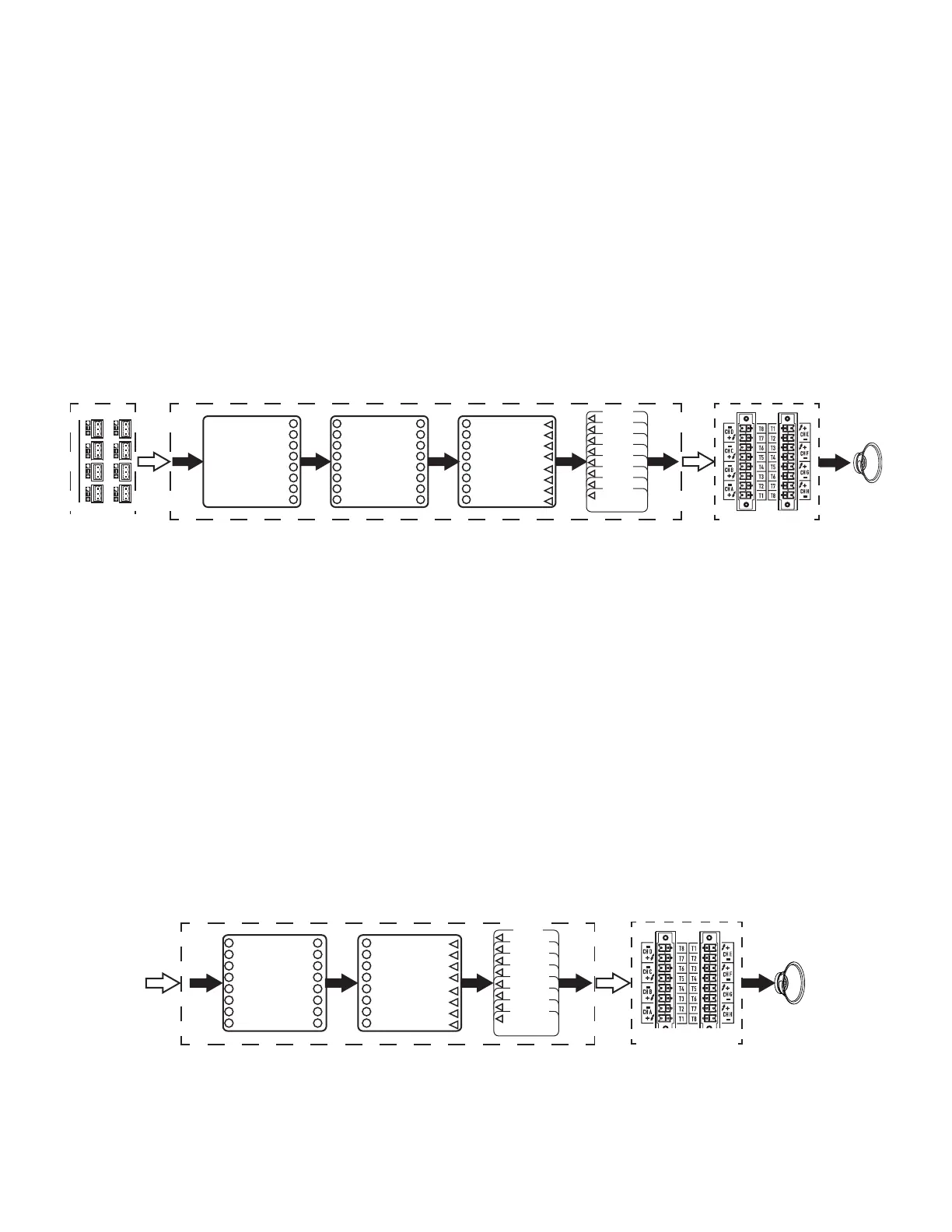
The CX-Qn model amplifiers have no analog inputs. The input signal utilized to drive the amplifier channels must be virtually wired in
Q-SYSDesigner.
1. Digital audio is sent to the Q-SYS Core via Q-LAN.
2. In the Core, the signals can be processed and sent anywhere within the Q-SYS system.
3. In the Q-SYS Core digital audio signals are sent to the Q-SYS Amp Output component.
4. The digital audio is then sent from the Q-SYS Core via Q-LAN to the amplifier.
5. Digital signals are converted to analog, amplified, and sent to the outputs of the amplifier.
The Q-SYS Amp Output component can have one to eight inputs/outputs depending on the amplifier model and its configuration in Q-SYS Designer.
The desired configuration is selected in the Q-SYS Designer Properties menu for the amplifier. When the amplifier's output configuration is changed,
all of the outputs are placed in a "mute all" state. You must unmute all in the Amp Output component's control panel or on the amplifier's front panel.
— Figure 15 —
Q-SYS Core
Q-LAN
Q-LAN
8-Channel Model Shown
Amplifier Rear
Panel Outputs
QSC
Loudspeakers
Q-SYS
DSP
Routing
Amp
Output
Amplifier-1
CX-Q
 Loading...