6
TD-001586-01-B
Installation
The following steps are written in the recommended installation order.
Rack-Mount the Amplifier
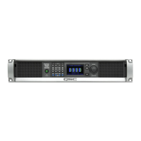
The CX-Q Series amplifiers are designed to be mounted in a standard rack-mount unit. The amplifiers are 2RU high, and 381 mm (15 in) deep.
1. Secure the amplifier in the rack with eight screws (not supplied), four in front, four in back. For complete instructions, refer to TD-000050 "Rear
Rack Ears Installation Guide" which can be found on the QSC Website (www.qsc.com)
CAUTION! Be sure that nothing is blocking the front or rear ventilation openings, and that each side has a minimum of
2cmclearance.
Wire Preparation
Use an appropriate wire-stripping tool to remove 7 mm of insulation from Input wiring and 10 mm of insulation from the Output wiring. Do not tin
the stripped wire ends.
Inputs
Q-LAN
– Connect the amplifier LAN A, and if available, LAN B, to the Q-LAN network (
Figure 3
). Refer to your Q-SYS documentation for network
requirements and connection detail.
— Figure 3 —
— Figure 4 —
— Figure 5 —
— Table 1 — Serial Number / Date Code Translation
Z WW YY XXXX
Sequential
4-digit base-29 (0-9, A-Z (excluding A,E,I,O,U,D,S), beginning with
0001 and reset at the beginning of each work week.
Year 2-digit calendar year (17 = 2017)
Work Week 2-digit calendar week number
N/A Not used for manufacturer date
Inputs
7 mm
1:1
Outputs
10 mm
1:1
— Figure 2 —

 Loading...