7
TD-001586-01-B
Analog Inputs
are converted to digital audio in the CX-Q amplifiers then routed to the Q-SYS Core over the Q-LAN network. The digital signals
show up in Q-SYS Designer at the CX-Q input component where they can
be routed as needed. Refer to the Q-SYS documentation.
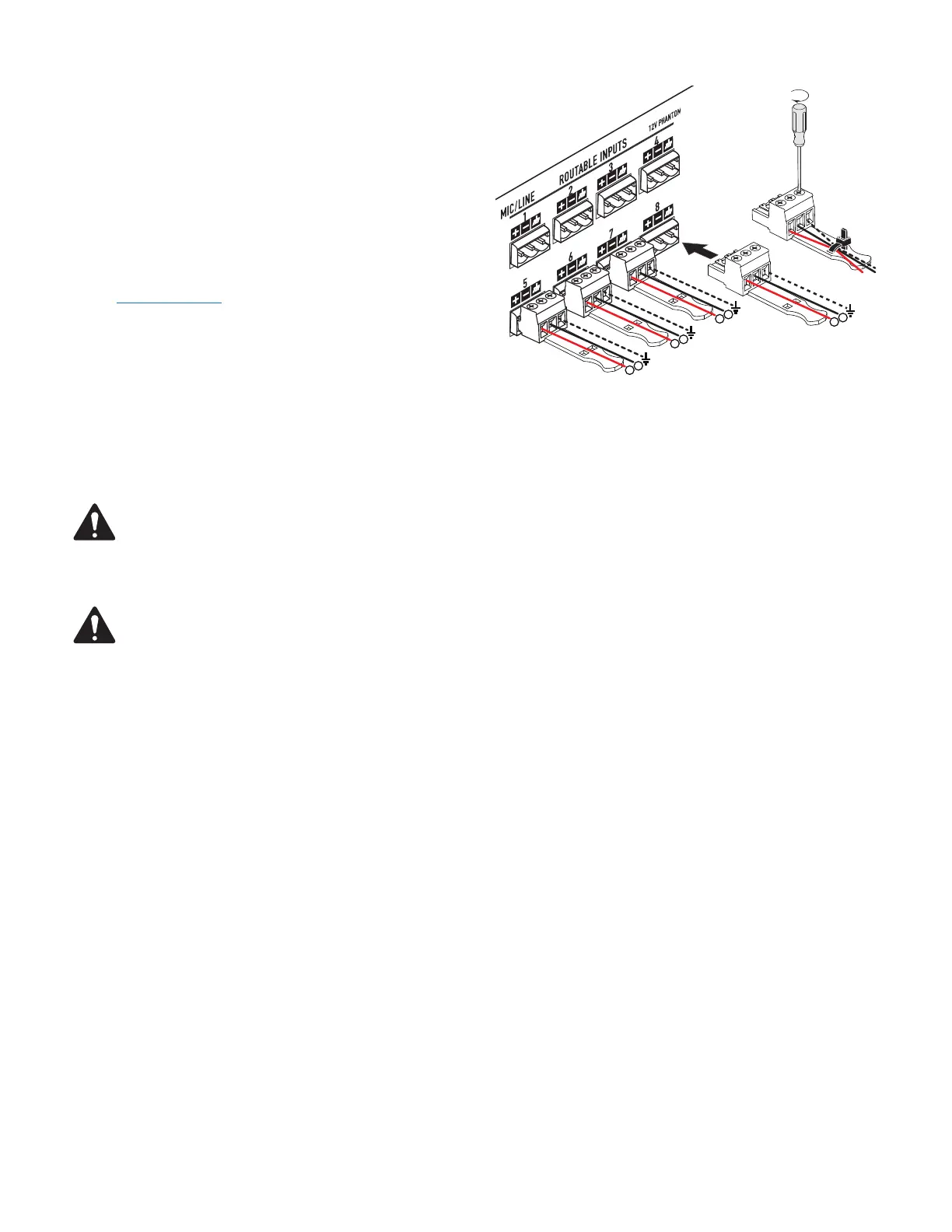
1. Make sure your audio source devices are powered off.
2. Wire the audio mic- or line-level source to up to eight (CX-Q 8-Channel)
or up to four (CX-Q 4-Channel) Euro-style connectors (supplied), you
can use either balanced inputs (
Figure 4
) or unbalanced inputs
(
Figure
5
).
3. Plug the connectors into the appropriate receptacles (Routable Inputs 1,
2, 3, 4, 5, 6, 7, 8)
Figure 4
and
Figure 6
.
GPIO
Refer to "GPIO" on page 16 for details about the GPIO feature.
Outputs and Output Configuration
The CX-Q and CX-Qn amplifiers have one or two sets of four-channel outputs
that are configured independently. The configuration of the amplifier is defined
in Q-SYS designer software and is "pushed" into the physical amplifier when
the Name and Type of amplifier in the design matches the Name and Type of
physical amplifier. Flexible Amplifier Summing Technology (FAST) allows users
to power a variety of loads through combining amplifier channels in various ways. Amplifier channels can be combined in BTL Bridged mode for higher
voltage needs or Parallel Mode for higher current needs.
Figure 7
thru
Figure 10
are examples of how the 4 channel amplifier blocks can be combined
to drive higher power requirements under different loads. Please reference the power output ratings for more information.
NOTE: The output connector is capable of handling up to 8 AWG for stranded wire.
Use the diagrams shown in
Figure 7
thru
Figure 10
as a reference for planning your loudspeaker configuration. Refer to
Figure 11
for how to
connect the wiring based on your configuration.
CAUTION! Before turning the amplifier on, double check your output connections to be sure they are connected properly based
on the output configuration specified in Q-SYS Designer.
If you change the output configuration of the amplifier you must change the loudspeaker connections before applying power to
theamplifier!
After a change of the output configuration, the amplifier re-boots and all outputs are muted. You must press the Mute All button in the
Q-SYS Amp Output component, Press The Amplifier Mode Button on the front panel of the amplifier.
Figure 7
through
Figure 10 are examples of the three types of output configurations: Separate, Bridged and Parallel. The tables to the right
and left of the loudspeaker connections (rear panel of the amplifier) give all the possible configurations and their connections. The following
diagrams show the 8-Channel models. 4-Channel models have outputs A through D only.
— Figure 6 —
-
+
-
+
-
+
-
 Loading...