9
TD-001586-01-B
ABCD 1 Channel, ABCD Parallel EFGH 1 Channel, EFGH Parallel
Parallel Channels (ABCD) and (EFGH)
— Figure 10 —
CHANNEL CONFIGURATION
1 Channel: A B C D
Channel Conguration Locked to Design
Q ABCD
CH ABCD
T3
+
T4
-
CH D
CH A
CH B
CH C
+
+
+
+
-
-
-
-
T8
T5
T6
T7
T4
T1
T2
T3
CH E
CH H
CH G
CH F
+
+
+
+
-
-
-
-
T1
T4
T3
T2
T5
T8
T7
T6
OUTPUTS TO SPEAKERS OUTPUTS TO SPEAKERS
CHANNEL CONFIGURATION
Channel Conguration Locked to Design
Q EFGH
1 Channel: E F G H
CH EFGH
T1
+
T3
+
T5
+
T7
+
T2
-
T4
-
T6
-
T8
-
In 4-1 Parallel (ABCD or EFGH) only
T1+, T3+, T5+, and T7+ are electrically the same point
T2-, T4-, T6-, and T8- are electrically the same point
SETTINGS CAN BE
CONFIGURED FOR
70V, 100V AND
200V DIRECT
OUTPUT.
Possible Combinations
The table below lists the options available in Q-SYS Designer.
For One Loudspeaker
Full power to one loudspeaker; Use one 2-wire cable, connect to:
• T3+/T4- (Loudspeaker ABCD)
For Multiple Loudspeakers
Full power for multiple loudspeakers in parallel Use up to four 2-wire
cables, connect to:
• T1+/T2- (Loudspeaker E)
• T3+/T4- (Loudspeaker F)
• T5+/T6- (Loudspeaker G)
• T7+/T8- (Loudspeaker H)
Outputs Configuration / Channels Outputs Configuration / Channels
A B C D 4 Channel E F G H 4 Channel
A+B C D 3 Channel, A B Bridged E+F G H 3 Channel, E F Bridged
A+B C+D 2 Channel, A B Bridged C D Bridged E+F G+H 2 Channel, E F Bridged G H Bridged
AB C D 3 Channel, A B Parallel EF G H 3 Channel, E F Parallel
AB C+D 2 Channel, A B Parallel C D Bridged EF G+H 2 Channel, E F Parallel G H Bridged
AB CD 2 Channel A B Parallel C D Parallel EF GH 2 Channel E F Parallel G H Parallel
AB+CD 1 Channel, A B Parallel Bridged with C D Parallel EF+GH 1 Channel, E F Parallel Bridged with G H Parallel
ABC D 2 Channel A B G Parallel EFG H 2 Channel E F G Parallel
ABCD 1 Channel A B C D Parallel EFGH 1 Channel E F G H Parallel
A B = Individual Channels, AB = Parallel Channels, A+B = Bridged Channels
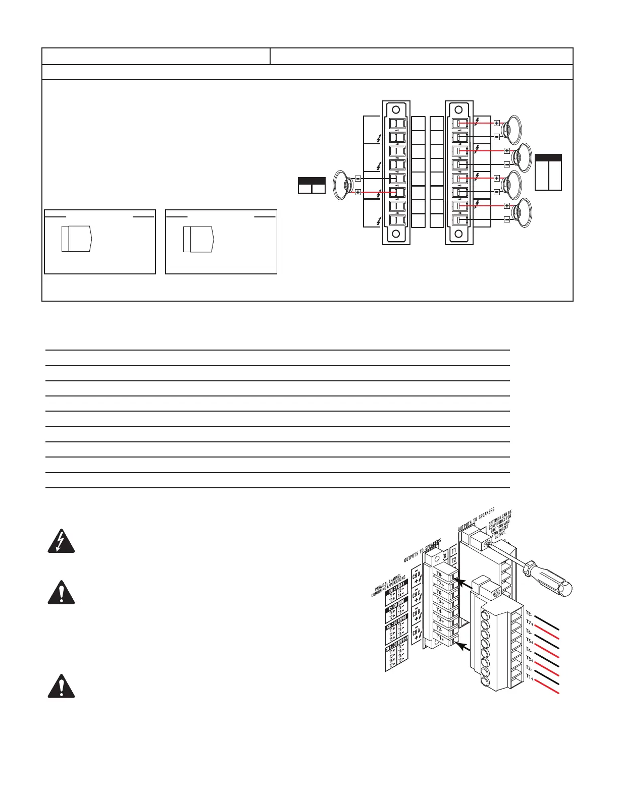
Connect the Loudspeakers
WARNING! There is a potential of having dangerous voltage at the
output terminals on the rear of the amplifier. Use caution not to touch
these contacts. Make sure the Power switch is off prior to making
anyconnections.
NOTE: The output connector is capable of handling up to 8 AWG for
stranded wire.
1. Connect the loudspeaker wiring to the 8-pin Euro-style connector as needed for your
amplifier's configuration.
2. Install the female 8-pin Euro-style connector onto the male connector on the rear of
the amplifier as shown in
Figure 11
.
3. Use a Phillips screwdriver to secure the connector.
IMPORTANT! The CX-Q series of audio power amplifiers are high
power amplifiers designed for installation use in both Lo-Z and Hi-Z
applications. Proper wiring class/size is required to ensure safe operation.
Based on operating mode, these amplifiers are designed for use with the
following speaker wiring:
• FAST Channel Configuration Mode: Single Channel & Parallel = Class 2 wiring
• FAST Channel Configuration Mode: BTL (140 V or 200 V modes) = Class3wiring
— Figure 11 —
 Loading...