14
TD-001586-01-B
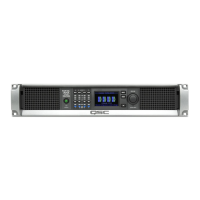
STANDALONE OUTPUT GAINS Screen
Refer to
Figure 19
The STANDALONE OUTPUT GAINS screens provide a quick overview of all outputs. In
addition, when this screen is displayed, you can make gain adjustments from the amplifier's
front panel. There is one screen for channels A–D and one for channels E–H.
Use the NEXT or PREV buttons to access these screens, or press one or more of the SEL
buttons to access the screen.
1. The highlighted background indicates that the Channel is selected by the SEL button.
2. Channel – the channels display according to the configuration of the amplifier.
3. Output Gain – the output gain can be controlled in two places: the GAIN knob on
the amplifier front panel and with the Gain control in the amplifier's Output component
in the Q-SYS design.
4. Q-LAN Input Level – the level of the audio signal applied to the Output component in the Q-SYS design. The CX-Q Output component is the
connection to the output section of the amplifier.
5. VOLTS – the voltage applied to that output.
6. In the example Output B is combined with Output A – (AB or A+B), the slot for Output B is blank.
To Make Gain Adjustments:
a. Use the SEL button to select one or more output channels. You can select any or all channels.
b. Use the GAIN knob to make adjustments to the output gain of the selected channels.
NOTE: If the gains were the same when you select multiple channels the gains remain equal as you adjust them. If the gains are
different, they keep their relative separation until one reaches a limit. At this point the other channel(s) continue to change until they
reach the limit.
NOTE: If you press one or more of the SEL buttons, and do not make any GAIN adjustments, this screen remains visible for a
short time then returns to the previous screen.
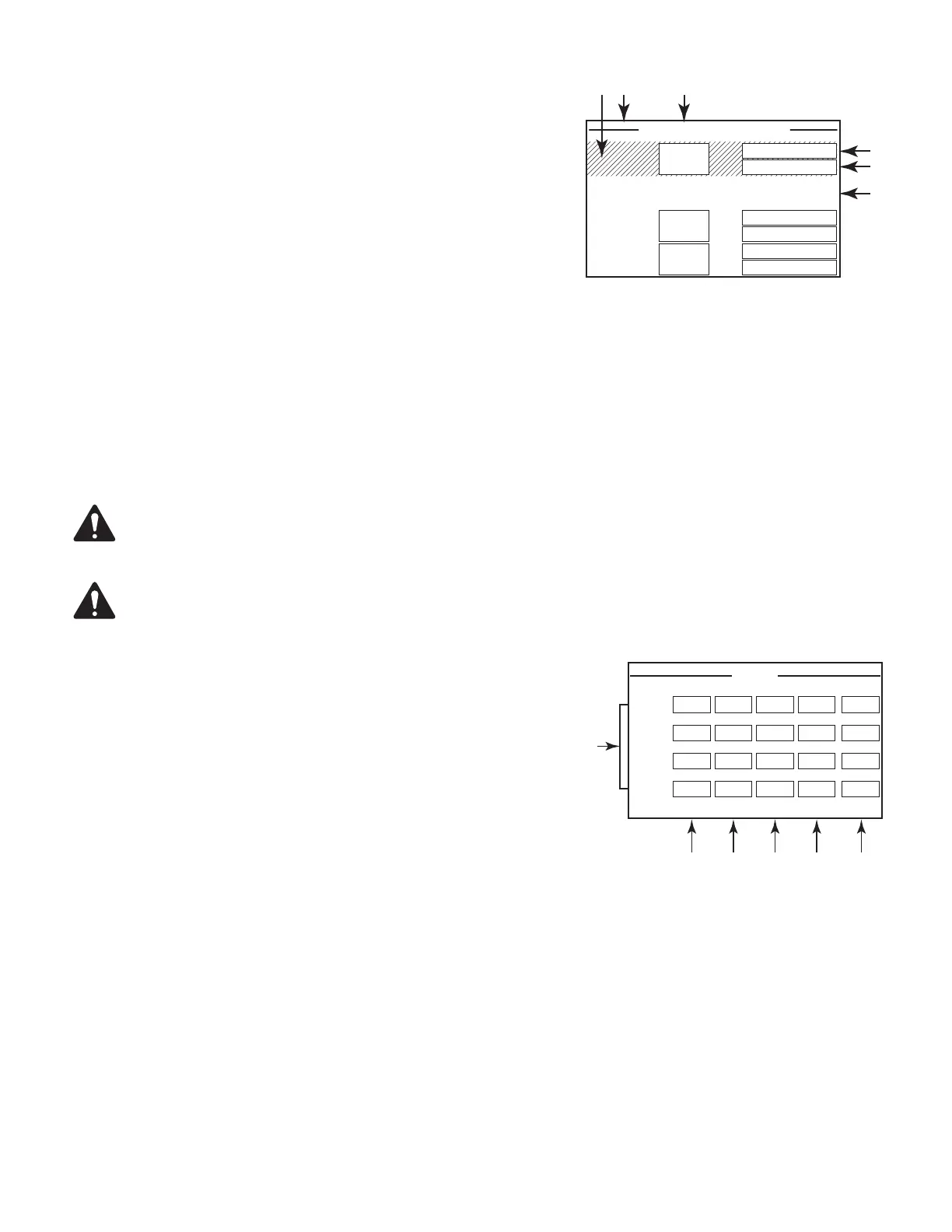
OUTPUT Screens
Each block of four outputs has a dedicated screen.
Figure 20
is an example of
OutputsA–D.
1. Output channel identifiers A – D and E – H (not shown).
2. DAC – when illuminated, this indicates that the signal to the D to A Converter is larger
than can be reproduced and a limiter has been engaged to prevent clipping.
3. PROTECT – when illuminated, this indicates that the amplifier is in Protect Mode.
Conditions can include over current, excessive long term average power output,
impedance too low.
4. LIMIT – when illuminated, this indicates the amplifier limiter is active. There are five
conditions that could cause the LIMIT condition:
• Power
• Current
• Voltage
• Temperature
• Loudspeaker Protection is active.
5. SHORT – when illuminated, this indicates the output is shorted. A short can be triggered by either of the following:
a. Output impedance is below ¼ Ω for more than 1 second.
b. Output voltage is less than 50% of what the DSP was expecting for more than 1 second.
6. Displays the temperature, in Centigrade, of the associated channel.
— Figure 19 —
STANDALONE OUTPUT GAINS
Q-LAN: -8.08 dB
VOLTS: 101 V
C
-100.0 dB
.014 V
Q-LAN:
VOLTS:
D
-100 dB
.014 V
Q-LAN:
VOLTS:
-45.0 dB
-45.0 dB
-45.0 dB
AB
— Figure 20 —
1
DAC PROTECT SHORT 41.05ºC
DAC PROTECT LIMIT SHORT 43.05ºC
A
DAC PROTECT SHORT 42.16ºC
B
DAC PROTECT SHORT 43.06ºC
C
D
OUTPUT
LIMIT
LIMIT
LIMIT
 Loading...