Do you have a question about the QSC MX 700 and is the answer not in the manual?
Details the three-year limited warranty for material and workmanship defects.
Important instructions to prevent electrical shock or fire hazards during use and servicing.
Explains the meaning of safety symbols like lightning flash and exclamation point.
Advises against using polarized plugs with extension cords to prevent blade exposure.
Welcome message and recommendation to review the manual.
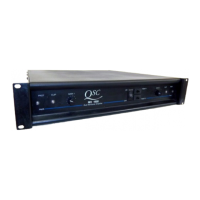
Describes the amplifier's design, features, and protection systems.
Instructions for checking the amplifier for damage after shipping and unpacking.
Critical safety and operational advice, including AC voltage check, speaker connections, and cover removal warnings.
Information on qualified personnel for servicing and warranty voiding.
Guidance on connecting speakers, using heavy gauge cables, and handling high voltages.
Warnings about internal circuitry, potential fire/shock hazards, and circuit breaker behavior.
Covers normal use of the amplifier in two-channel or stereo applications.
Specifies connecting the AC cord to a standard outlet and voltage range.
Explains the lack of chassis ground lifting and use of balanced inputs for hum rejection.
Details input polarity for 1/4-inch plugs and barrier strips, and grounding unused terminals.
How to connect banana plugs, spade lugs, or bare wire ends to binding posts, noting polarity.
Steps for powering up the amplifier, checking LED indicators, and muting behavior.
Explains gain settings, LED indicators (Clipping), and muting for turn-on/off thumps.
Description of the two-speed fan, airflow, and rack mounting recommendations for cooling.
Refers to illustrations in Section 2 for input connection details.
Explains the electronic balanced input and impedance matching for optimal performance.
Proper cabling for balanced line operation, keeping the shield separate from signal conductors.
How the input circuit responds to unbalanced signals and grounding unused terminals.
Specifies input polarity for 1/4-inch plugs and barrier strips, and how to wire for stability.
Instructions on how to connect inputs of multiple channels to the same signal source.
How to engage bridged mono mode, connect speakers, and match gains.
Warnings regarding minimum impedance, cable connections, and load limits for bridged mono.
Description of the red and black 5-way binding posts on the rear chassis.
Identifies the red post as positive/hot and the black post as ground return.
Notes the possibility of shock hazard at speaker terminals due to high power.
Recommendations for using heavy gauge, finely stranded wiring for optimal performance.
Emphasizes observing correct polarity at both speaker and amplifier ends.
Discusses the amplifier's capability with different impedances (2, 4, 8 ohms) and potential issues.
Information on using the amplifier with 25-Volt, 70-Volt, and 100-Volt distributed sound systems.
Explains the desirable rolloff below 50Hz in commercial sound systems.
Lists various protection features like short circuit, over-temp, and RF protection.
Describes protection for inputs (resistors) and outputs (ultrasonic network).
Explains the function of the green Power LED and red Clip LEDs.
General advice for isolating problems by comparing channels and checking connections.
Common causes and troubleshooting steps for a complete lack of audio output.
Potential causes like low input signal, incorrect gain, or speaker driver failure.
Suggests checking for misadjusted units, bad speakers, or input overload.
Likely causes include bad connections, intermittent signals, or overheating.
Issues with frequency response are usually traced to speakers or preceding units.
Discusses perceived lack of power, speaker efficiency changes, and room acoustics.
Covers common audio noise issues like hum, buzz, and hiss.
Describes crackling noise and its causes, including defective electronics or bad connections.
User responsibility to determine and operate within speaker limits.
Explains how the amplifier protects speakers from DC transients below 20Hz.
Emphasizes user responsibility for loudspeaker damage from overpowering or incorrect operation.
Instructions for cleaning the faceplate and chassis with a soft cloth and mild cleaner.
How dust buildup affects cooling and requires qualified service for thorough removal.
States no periodic tune-up adjustments are needed, but external screws can be checked.
How to find authorized service centers and precautions for returning the unit for repair.
Lists output power ratings for different impedances and THD levels.
Specifies output power for bridged mono configuration at various impedances.
States the dynamic headroom specification at 4 ohms.
Lists THD and SMPTE-IMD specifications for different conditions.
Details the frequency response range and its deviation at 1 watt.
Provides the damping factor specification at 8 ohms.
Specifies the noise level relative to rated power.
States the input voltage required for rated output at 8 ohms.
Lists the gain setting in dBV.
Specifies impedance for unbalanced and balanced inputs.
Lists front panel controls like AC Switch and Gain Knobs.
Lists front panel indicators: Power LED and Clip LEDs.
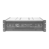
Lists rear panel connectors for inputs and speakers.
Describes the 2-speed fan and airflow direction.
Lists various protection features like short circuit, over-temp, and RF protection.
Details AC coupled output and muting for load protection.
Specifies the number of output devices.
Describes the power supply components like transformer secondaries and filter capacitors.
Lists the available AC voltage and frequency requirements.
Provides physical dimensions including rack mounting height and depth.
Lists the net and shipping weight of the amplifier.
Notes explaining various aspects of the circuit diagram, including component types and connections.
A chart detailing connections for different voltages and internal wiring.
| Channels | 2 |
|---|---|
| Power Output (4 ohms) | 700 W |
| 8 Ohm Stereo (per channel) | 350 W |
| 4 Ohm Stereo (per channel) | 700 W |
| 8 Ohm Bridged | 1400 W |
| Signal to Noise Ratio | > 100 dB |
| Frequency Response | 20 Hz - 20 kHz |
| Input Sensitivity | 1.4 V |
| Input Impedance | 20 kΩ |
| Damping Factor | > 200 |
| Cooling | Convection |