Do you have a question about the QUAD EZ-7000 and is the answer not in the manual?
Ensures EZ-7000 installation adheres to ANSI 156.19 for low energy.
Emphasizes the ES500 control must stay connected to prevent uncontrolled speed.
Guides through initial wiring, power, and cam checks for setup.
Explains synchronized delay settings (d1, d3) for dual operators.
Warns that improper installation/adjustment can cause injury and damage.
Mandates installation and adjustment by a certified professional.
Requires daily inspection; disable if malfunctioning until repaired.
Prohibits self-adjustment or repair; contact supplier.
Explains the manual's goal to familiarize users with the system and safety standards.
Assigns owner responsibility for daily operation checks after power loss.
Details the 12-month warranty against material and workmanship defects.
Explains products are distributed via authorized distributors for sales and service.
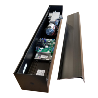
Identifies the location of cams on the ES-500 board.
Indicates the 120V power input terminal.
Identifies adjustment pots for speed and limit settings.
Shows the location of the programming buttons.
Specifies installation by experienced, trained installers per ANSI A156.19.
Details EZ-7000 application limits (interior, width, weight) and opening angle.
Warns against connecting power until instructed.
Recommends wood studs or blocking for header mounting support.
Instructs on lifting and bolting the unit into the header, centering the shaft.
Warns against rotating the motor before controller installation to prevent damage.
Details installing the HOA switch and connecting its harness.
Instructs to install the rod swivel according to dimension charts.
Guides preparation of the power arm and rod using provided charts.
Provides dimension tables for various hinge types and reveals for arm/rod setup.
Illustrates in-swing and out-swing configurations for arm and rod placement.
Details installing the track on the door, including dimensions and screw type.
Instructs setting the unit to "Hold Open" to rotate the shaft.
Describes placing the arm under the output shaft and inserting the pin.
Explains how to change the arm's orientation (hand).
Stresses ES-500 installation must comply with ANSI 156.19.
Guides on installing the HOA switch and connecting its lace to the control.
Details connecting incoming power wires and ground to the operator.
Explains how to adjust parameters using the UP/DOWN/SET buttons.
Instructs to save parameter changes by holding the SET button.
Details adjusting latch check switch, close speed, and latch speed pots.
Guides on checking open check switch cam and setting limit/obstruction pots.
Explains how to test door cycling using the DOWN button.
Introduces limit and obstruction sensing for safety.
Instructs on wiring actuating devices to the ACT connector (CN2).
Describes connecting and configuring automatic locks.
Guides on powering up after wiring and checking indicator lights.
Lists and explains the status codes displayed by the ES500 control.
Introduces the list of adjustable parameters in the ES500 control.
Explains the OS parameter for setting opening speed.
Details the D3 parameter for delay after closing obstruction recycle.
Explains the LC parameter for delay before latch check.
Details the UL parameter for ensuring lock retraction before opening.
Describes the AF parameter for configuring auxiliary input functions.
Reaffirms that d1 and d3 must be identical for synchronized operators.
Provides measured currents and power consumption figures for the EZ-7000.
Estimates higher opening power when a door is attached.
Estimates the cost of operation per door cycle and per month.
Details pin assignments for the CN8 Lock connector.
Details pin assignments for the CN7 AUX connector.
Details pin assignments for the CN6 SAFETY connector.
Details pin assignments for the CN4 SWTCH connector.
Identifies receiver terminals and their functions.
Shows how the wiring harness connects to the ES-500 control board at CN3.
Illustrates wiring for Option #2 with the Larco Ultra Small Receiver.
Shows the recommended wiring diagram for a lock using a transformer.
Details CN8 lock pinout for connection to BEA wireless receiver.
Details CN7 AUX pinout for connection to BEA wireless receiver.
Details CN6 SAFETY pinout for connection to BEA wireless receiver.
Details CN4 SWTCH pinout for connection to BEA wireless receiver.
Contact information for BEA technical support in the East Region.
Wiring diagram for the Eagle 1 approach side door mounted sensor.
Wiring diagram for the Bodyguard 1 sensor system.
Notes on troubleshooting, support contact, and leaving doors inoperable if unresolved.
Wiring connections for Optex sensors to CN7 AUX.
Wiring connections for Optex sensors to CN6 SAFETY.
Wiring diagram for the Optex OA Edge safety sensor.
Contact number for Optex technical support.
Details CN8 lock pinout for Optex 904C connection.
Details CN7 AUX pinout for Optex 904C connection.
Details CN6 SAFETY pinout for Optex 904C connection.
Details CN5 SYNC pinout for Optex 904C connection.
Discusses compatibility of EZ-7000 with Horton controls and required adapter harness.
Step-by-step instructions for adjusting the door operator cams.
Details configuring a motion sensor as a recycle/hold open device.
Guides on installing swing side sensors using a safety harness.
Explains the function of the "UL" (Unlock) setting.
Describes how a safety mat operates with the ES-500.
Details support for safety beams in high energy mode and related parameters.
Discusses the MOV and Surge Limiter for spike protection.
Lists default programming for the 4000 Series ES-500 board with a specific chip.
Notes programming items unique to the EZ-7000/28k operator.
Emphasizes that the LL function must be enabled when installing a lock.
Refers to a supplement for programming Power Assist Chips.
| Brand | QUAD |
|---|---|
| Model | EZ-7000 |
| Category | Door Opening System |
| Language | English |