Quadra-Fire • QV36DB-A • 2018-900 Rev. F • 12/07
6
1
2
3
4
5
6
7
8
9
10
11
12
13
14
15
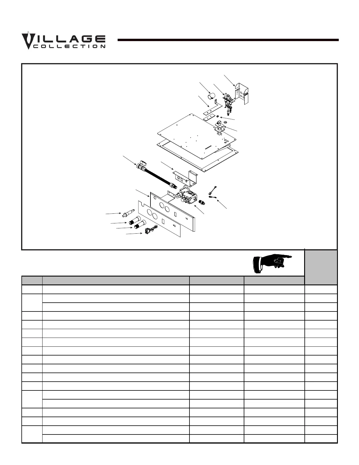
Valve Assembly Diagram
Service Parts
QV36DB-A
Beginning Manufacturing Date: June 2003
Ending Manufacturing Date: ______
Standing Pilot Ignition
Valve Assembly
ITEM DESCRIPTION SERIAL # PART NUMBER
1 Pilot Bracket 2018-107
N
Pilot Assembly NG 530-510A
Y
Pilot Assembly LP 530-511A
Y
3 Shutter Assembly
319-316A
Y
4 Shutter Bracket Assembly
2026-017
Y
5 Valve Bracket 550-169
N
6
Flex Ball Valve Assembly 302-320A
Y
7 Control Panel 295-119
N
8
Piezo Ignitor 291-513
Y
9 Pilot Control Knob 571-530
Y
10
Flame Control Knob 571-531
Y
11 ON/OFF Rocker Switch 060-521A
Y
Valve NG 060-522
Y
Valve LP 060-523
Y
13
Wire Assembly 049-552A
Y
14
Flexible Gas Connector 383-302A
Y
Orifice NG (3.1 MM)
582-8310
Y
Orifice LP ( 1.8 MM)
582-818
Y
15
12
2
Stocked
at Depot
IMPORTANT: THIS IS DATED INFORMATION. When Requesting service or
replacement parts for your appliance please provide model number and serial number.
All parts listed in this manual may be ordered from an authorized dealer.
Î
 Loading...