Do you have a question about the QuadTech Sentry Plus Series and is the answer not in the manual?
Instructions for inspecting the Sentry Plus Series instrument upon receipt and handling packaging.
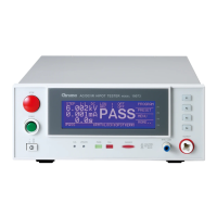
General description of the Sentry Plus Series Hipot Tester capabilities and features.
Identification and function of front and rear panel controls and indicators on the instrument.
Information regarding instrument dimensions, positioning, power requirements, and safety checks.
Definitions of technical terms and measurement unit prefixes used in the manual.
Procedure for powering on the Sentry Plus Series instrument and initial warm-up.
Overview of the Sentry Plus Series instrument's test capabilities and programming steps.
Step-by-step instructions for programming a Ground Continuity (GC) test.
Detailed guide for programming the AC Hipot test parameters.
Detailed guide for programming the DC Hipot test parameters.
Detailed guide for programming the Insulation Resistance (IR) test parameters.
Instructions for programming a PAUSE mode within a test sequence.
Procedure for saving programmed test setups into the instrument's memory.
Guidance on programming sequential tests (up to 10 steps) on the instrument.
Configuration of initial parameters and default conditions for tests.
Procedure for performing automatic offset for lead and fixture effects.
Illustrates connections for testing a single device under test (DUT) using standard cables.
Steps to initiate and perform a measurement test, including pass/fail judgments.
List and description of error messages displayed upon a NO GOOD/FAIL judgment.
Accessing and configuring programmable instrument parameters via the MENU.
Functionality for storing, recalling, or deleting test setups and preset values.
Configuration of system parameters like contrast, beeper volume, and specific limits.
Details on available option parameters, such as multi-link functionality.
Information on accessing the instrument calibration routine, requiring service personnel.
Procedure to lock out front panel functions like PROGRAM, PRESET, and MENU.
Instructions for activating and changing the instrument's password.
Functionality to track invalid remote commands via an error log.
Displays instrument manufacturer, software version, and copyright information.
Description of remote control connectors and their input/output signals for external operation.
Instructions for connecting to the G16 International Power Strip for testing corded products.
Procedure for using the S07 adapter cable for testing products via their AC inlet module.
Instructions for connecting corded products using the S03 adapter.
Details on connecting the S05 Foot Switch for hands-free remote testing.
Instructions for connecting and using the S08 Gun Probe for pinpoint control testing.
Information on connecting the Sentry Plus to the S50 Plus for high current ground testing.
Overview of warranty, technical assistance, and distributor information.
Procedure for returning the instrument for service, including RMA and shipping instructions.
Recommendations and general procedures for instrument calibration.
Lists required equipment and calibration parameters for various tests.
Steps to enable the calibration function, including password entry.
Detailed steps for calibrating AC voltage measurements.
Detailed steps for calibrating DC voltage measurements.
Detailed steps for calibrating Insulation Resistance (IR) voltage measurements.
Detailed steps for calibrating AC current measurements using resistance loads.
Detailed steps for calibrating DC current measurements using resistance loads.
Calibration steps for the Ground Continuity (GC) test.
Final steps to complete calibration, including password and confirmation.
| Brand | QuadTech |
|---|---|
| Model | Sentry Plus Series |
| Category | Test Equipment |
| Language | English |