Page 20 of 85
Condensed Operating Instructions (Continued)
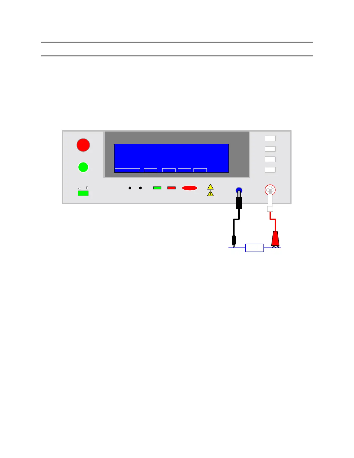
Connection to Device under Test (DUT)
Figure COI-4 illustrates the connection of the Sentry Plus Series unit to a single DUT using the
S02 1-meter HV cable set that comes standard with the instrument. The custom white banana
plug/red alligator clip is connected between the OUTPUT terminal on the Sentry Plus Series unit
and the high side of the device under test. The black banana plug/alligator clip is connected
between the RTN/LOW terminal on the Sentry Plus Series unit to the low side of the DUT.
DUT
S02
Cable
Set
+-
F1
RTN/LOW
F2
OUTPUT
DANGERPASS FAIL
F1
F2
F3
F4
START
STOP
Sentry 30 Plus AC/DC/IR Hipot Tester
01
Q
uadTech
!
CAUTION
F4
F3
Max 5kVAC
6kVDC
CAL UPDATE
1.250kV
STEP 1/5
STAND BY OFST
0.500mA
3.0s
AC
LOW: OFF
ARC: OFF
RAMP: OFF
FALL: OFF
PROGRAM
PRESET
MENU
M1
RMT LOCK ERR
MORE..
COI-4: Connection to Device under Test
Measurement Mode
1.
Turn [POWER] ON.
2.
Allow Sentry Plus Series instrument a 15-minute warm up time.
3.
Connect S02 Black ground cable to Sentry Plus Series unit RTN/LOW terminal
4.
Connect S02 White/red HV cable to Sentry Plus Series unit OUTPUT terminal.
5.
Press [F1] = PROGRAM and enter test parameters. When finished programming, press
[F4] = EXIT to return to STAND BY status.
6.
Press [F4] = MORE to access Offset function. Press [F3] = OFFSET. Follow Offset
instructions. When Offset is complete, press [F4] = MORE to return to STAND BY.
7.
Connect device under test (DUT) to test leads.
8.
Press [START].
9.
Record measurement.
10.
Press [STOP].